Author response:
The following is the authors’ response to the original reviews.
Reviewer #1 (Public review):
The work corroborates the idea, recently suggested by Rosenthal et al. (2025), that spreading depolarization is involved in the mechanisms of electroconvulsive therapy. Using a mouse model of electroconvulsive therapy and various sophisticated approaches to visualize cortical activity, the authors provide an extensive description of traveling calcium waves induced by electroconvulsive stimulation. The study confirms that the calcium events have properties typical of cortical spreading depolarization and seeks to show that the calcium/SD waves mediate therapeutic and neuroplastic effects of electroconvulsive therapy. The authors find that after electroconvulsive stimulation associated with calcium/SD waves, Fos expression increases widely; in the cortex, this increase is localized to the hemisphere affected by calcium waves. They show that some EEG predictors of the beneficial effects of electroconvulsive therapy correlate with the occurrence of calcium/SD waves. Despite the solid methodology and the study's interesting, its conclusions are not fully supported by the data.
In particular:
(1) The title of the paper claims that "electroconvulsive stimulation drives cortical spreading depolarization dependent immediate early gene expression". However, immunohistochemical staining shows that Fos expression increases not only in the cortex but also in many subcortical regions, including the hippocampus and amygdala (Figure 5A). Really, conventional electroconvulsive therapy stimulates nearly the entire brain volume and induces generalized seizure activity that can trigger SD not only in the cortex but also in other brain sites. Therefore, regions beyond the cortex can also drive the effects of electroconvulsive therapy.
This is correct, our claim is that ECS drives spreading depression dependent IEG expression in cortex. We are not claiming this is the only consequence of ECS. The extracortical response to ECS could contribute to the treatment, and we discuss this in the hippocampus specifically (see Discussion). In current clinical practice, cortical surface EEG is used as a biomarker for predicting treatment outcome. Given that the CSD is necessary to drive Fos expression in cortex, we think it is warranted to speculate that monitoring CSD during ECT is worth exploring as a potentially superior biomarker of treatment outcome. Especially given that this is readily feasible (Discussion).
Next, the authors use Fos staining as a marker of neuronal plasticity. However, Fos is also a marker of preceding neuronal activation. As electroconvulsive stimulation, seizures, and SD are associated with high neural activity, it is unclear whether the observed Fos upregulation results from the prior activation or heralds the subsequent plastic changes. Other markers of neuroplasticity (e.g., BDNF) should also be examined.
The idea that Fos is a marker of neuronal activity is outdated. The primary correlate of Fos expression is neuronal plasticity and learning-related circuit modifications, rather than just neuronal activity – see e.g. (Bolhuis et al., 2001; de Hoz et al., 2018; Fleischmann et al., 2003; Kimpo and Doupe, 1997; Mahringer et al., 2022, 2019; Nakadate et al., 2012; Roy et al., 2016; Ryan et al., 2015; Tanaka et al., 2018; Tyssowski et al., 2018; Watanabe et al., 1996; Yassin et al., 2010). We have now referenced some of those articles in the manuscript (Introduction). But more importantly, our claim is that the CSD is necessary to drive Fos. The fact that CSD can occur in a single hemisphere allows, within a brain, to control for direct ECS response and phase III oscillations. In unilateral CSD, contralateral hemispheres displayed Fos levels in the cortex that were similar to sham mice. Investigating the exact plasticity pathway that is triggered by the CSD is an interesting question we are pursuing in follow-up work, but does not influence our conclusions here.
(2) Postictal EEG suppression is one of the most promising correlates of positive clinical outcomes after electroconvulsive therapy. Cortical SD is also tightly coupled with suppression of neuronal activity in affected regions. Although the authors report that postictal suppression is stronger after stimulations with cortical SDs than without SDs, the cortices affected (ipsi) and unaffected (contra) by unilateral cortical calcium/SD events exhibit identical suppression (Figure 6F). The result contradicts established knowledge in the field. If the calcium events are cortical SDs, they should induce EEG suppression only in the affected hemisphere.
The reviewer is correct in that postictal suppression is currently one of the best correlates of positive clinical outcome used in the clinic. However, note that EEG-based correlates are generally weak predictors of treatment outcomes: even recently identified correlates are unreliable between patients cohorts and account for less than 60% of the clinical outcome (Francis-Taylor et al., 2020; Scangos et al., 2019). See also our response to comment (2) of reviewer 3 on this topic.
The primary problem in the interpretation of postictal suppression of EEG activity is that it is unclear what the source of the EEG signal is in this case. During phase III oscillation following the CSD, cortex is silent and all of the EEG is likely driven by thalamic input to cortex. Note, source localization in EEG does not help as the source of the signal is likely the thalamic axons in cortex (Huels et al., 2023) (or their postsynaptic, and in this case subthreshold, effects). Whatever the source of the cortical surface EEG may be, we know that following CSD it cannot be cortical activity, hence, whatever is driving postictal suppression is also not cortical. If we had to speculate, postictal suppression is likely an exhaustion of thalamus in attempting to drive cortex without getting any excitatory feedback. During an epileptic seizure, thalamus oscillates at delta frequencies and cortex responds at each peak of the oscillation, generating ictal spikes on the EEG (Meeren et al., 2002; Polack et al., 2009). The fact that ictal spikes are missing in an “optimal” phase III oscillation is consistent with our findings that the CSD completely silences cortex for minutes. Thus, during an ECS-driven phase III oscillation, cortex does not respond to thalamic input and at some point thalamus runs out of energy to maintain the oscillation - it is likely the combination of thalamus running out of energy and a silent cortex that gives rise to postictal suppression. Note we do find an asymmetry for the mid-oscillation amplitude (Figure 6A), which in this interpretation can be explained by the thalamo-cortical circuit attempting to compensate for the absence of cortical feedback by increasing its drive to the CSD-affected hemisphere.
(3) The study states a beneficial role of calcium/SD waves in ECS effects. However, SD alters numerous aspects of brain function, leading to a range of effects that can underlie side effects as well. Assessment of the behavioral effects of stimulation with and without calcium/SD waves can help clarify the issue.
This is a misunderstanding. We claim (and show) that the CSD is necessary to drive immediate early gene expression following ECS. Based on this we speculate that the CSD “may serve as a more relevant biomarker for predicting and optimizing therapeutic outcomes of ECT” than EEG biomarkers.
We do not “state [that there is] a beneficial role of CSD” – we actually address the possibility that SD may not be therapeutically beneficial (Discussion). The suggestion of investigating behavioral consequences of CSD in mice is interesting, but likely not the most relevant follow-up work. This is for two reasons:
(1) Very different from humans, most mouse behavior does not depend on cortex (Kawai et al., 2015; Pandey et al., 2026). Thus, any potential behavioral consequences of ECS in mice are difficult to interpret in the context of clinical relevance. We don’t think there is any known biomarker based on mouse behavior that has any direct translational value to psychiatric treatments. The reviewer may disagree with this assessment but just consider that no mouse behavior assay has ever been instrumental to the development of a novel psychiatric treatment.
(2) The more direct – and simpler approach – is to directly test whether CSD correlates with treatment outcomes in patients. Our primary aim with this paper is to inspire exactly this. Note, we are currently pursuing this as well, of course. Monitoring CSDs in humans during ECT is likely possible with fNIRS or other hemodynamic-based measurements (Discussion).
However, to reiterate – the claim of the manuscript is exactly as stated in the title. Thus, demonstrating the clinical relevance of the CSD is outside of the scope of the current manuscript, but will be trivial to prove by measuring treatment outcomes while routinely monitoring patients for CSD.
The results of the work suggest that cortical SD can contribute to electroconvulsive therapy-related mechanisms and help to optimize the stimulation parameters to achieve maximal therapeutic effect.
Reviewer #1 (Recommendations for the authors):
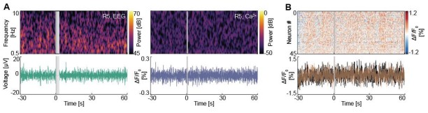
The results of sham tests are shown only for the immunohistochemical data. However, results from control experiments should be provided for the EEG and calcium data.
Sham data are included in Author response image 1. We are not sure how they support our conclusions and have left them out of the manuscript. A sham stimulation just characterizes ongoing activity under anesthesia. The more direct comparison is the difference between pre- and post-ECS activity. Baseline widefield calcium imaging data is already shown in Figure 1, 2, 6; baseline mouse EEG data is already shown in Figure 1 and 6. Baseline EEG in patients is not available in the present dataset.
Author response image 1.
Sham ECS does not result in phase III oscillations or a CSD. (A) Representative spectrograms (top) and raw traces (bottom) of concurrent EEG (left) and widefield calcium imaging (right) during a sham ECS session. (B) Population raster plot (top) and two example activity traces of neurons (bottom) during a sham ECS two-photon recording.
Moreover, baseline (pre-ECS) calcium and EEG activity should be shown in Figures 1 and 6 to correctly assess the changes induced by stimulation.
We are not sure we understand as pre-ECS data are already shown in Figures 1 and 6. We assume the reviewer may mean “more baseline data should be shown”? We have extended the time scale of the relevant panels in Figure 1, 2 and 6 to include 30 s instead of 10 s of pre-ECS data.
Using the term 'oscillations/phase III oscillations' instead of 'seizures' throughout the text is confusing because the word covers a wide range of brain oscillations - from normal to pathological ones.
This is indeed confusing – but the confusion arises from the often imprecise usage of the term “seizure” in the ECT literature. The EEG response to ECS is not equivalent to that of an epileptic seizure. The description of a “phase III oscillation” is a more precise description of the EEG signature. It was introduced by (Brumback and Staton, 1982) and is not our terminology. We dedicate an entire paragraph in the introduction to this distinction. We are not sure how to make this clearer in the current manuscript. Continuing to describe the EEG response to ECS as “seizure” is inaccurate, and mechanistically misleading, especially given that cortex is silent during the phase III oscillation following the CSD (i.e. cortex cannot be “seizing” during this phase of the EEG response, see our point above on postictal EEG suppression).
The presentation of clinical data is scarce and unclear. e.g., the authors claim that the oscillation frequency is similar in mice and humans (lines 206-208). However, in Figure 1F, oscillations during the early post-ECS phase have twice the frequency (6-7 Hz) in the patient EEG recording (6-7 oscillations per 1 second) compared to the mouse EEG (3 Hz, i.e., 6 oscillations per 2 seconds during 73-75 s). It seems a bit odd because Figure 1H shows that the frequency does not exceed 5 Hz, even in patients.
Please excuse, this is our mistake. The x-axis label in the human data of Figure 1F was incorrect. It should have read 1 to 3 s, not 1 to 2 s. Window sizes were of course matched between mice and human data and are all 2 s. The mistake is now corrected. The frequencies in patients and mice are compared in Figure 1H and are not different.
A part of the discussion (lines 627-635) is based on factual inaccuracy: cortical SD cannot invade the hippocampus in the in vivo brain (only in slices), although SD can occur in the hippocampus in response to generalized seizures.
It would be helpful if the reviewer would back up this claim with references. Short of this we are left to speculate - we suspect the reviewer may be referring to earlier work in the rat cortex, that claimed that a cortical SD can only invade hippocampus if glia has been impaired (Largo et al., 1997). This is now an outdated model: there are more recent reports of CSD invading the hippocampus (Bahari et al., 2020; Bonaccini Calia et al., 2022). If the reviewer has specific concerns with any of these papers, we would be happy to discuss in more detail, but the reviewers’ claim seems unfounded here.
It is reasonable to expect that bilateral stimulation produces bilateral calcium/SD waves. In Rosenthal's experiments, this situation was most common. In the present study, bilateral ECS triggers mostly unilateral calcium waves. Do you have any idea what the reasons for the result are? As stimulation parameters (polarity, intensity, and frequency) have been shown to control the occurrence of SD waves, their unilateral pattern suggests non-uniform stimulation conditions. I am curious whether the uni- or bilateral pattern of calcium/SD waves depends on the ECS parameters.
The main difference between our patient and mouse data is the polarity of stimulation. For patient data, the polarity of the current alternates with every pulse, while in our mouse data the stimulation was always right unipolar. This is discussed when we mention the asymmetry of SD in our data (Results, Methods) - we suspect the reviewer may have missed this.
Reviewer #2 (Public review):
Summary:
This manuscript addresses the question of mechanisms underlying the therapeutic effects of electroconvulsive therapy (ECT). Clinical efficacy of ECT in major depression (and other disorders) is well established and has often been assumed to be a direct consequence of seizure activity generated by the current application. However, as the authors point out, this explanation is unsatisfactory. A recent study (Rosenthal et al., 2025) provided evidence that ECT generates a wave of cortical spreading depolarization (CSD) in mice, and initial evidence that similar events were generated in patients undergoing ECT. Based on their observations, Rosenthal et al. proposed that CSD, rather than seizure, may engage plasticity mechanisms that contribute to the brain's clinical response to ECT. The current study adds to that prior work by reporting other consequences of CSD, in addition to sustained Ca2+ elevations. The current study also links EEG characteristics immediately following the ECT with the likelihood of generating a CSD, which can help optimize ECT parameters.
Strengths:
An important research topic, linking a large set of rodent studies with a limited clinical EEG data set.
The data acquisition and analyses appear to be of very high quality, and the main results are well illustrated.
Association between EEG characteristics linked to good clinical outcome matched by mouse EEG data linked to CSD.
Characterization of multiple consequences of CSD following ECT in the mouse brain.
Weaknesses:
(1) The main characterization of CSD propagation comes from GCaMP Ca2+ measurements, as previously reported (Rosenthal et al., 2025). That prior study also provided key electrophysiological evidence of CSD with a DC shift after ECT in mice (supplemental data). Given the prior evidence for ECT-CSD, the additional measures shown in the current manuscript are fully expected. Thus, the 2-photon imaging of Ca2+ elevations following CSD (Figure 4) is consistent with prior 2-photon imaging studies of CSD, and the complex hemodynamic and pH changes are expected to contribute to propagation of EGFP fluorescence changes (Supplemental Figure 5). These data are well presented, but, contrary to the results section here, these results appear confirmatory rather than necessary to build a case that the key event generated by ECT is a CSD.
This is correct, our work confirms that the calcium event following ECS is a CSD. The main claim of our paper is that ECS drives immediate early gene expression in a CSD-dependent manner.
However, note that the Rosenthal paper concluded that the calcium event is a CSD while providing only little evidence for that claim – mind you, we agree with their interpretation, but provide more evidence for the conclusion. We are happy to discuss the limitations of the Rosenthal paper as highlighted below more prominently in the manuscript, if the reviewer thinks this would be helpful, but we think that is likely not necessary.
Briefly, in the data presented in (Rosenthal et al., 2025), the only support for the calcium response being a CSD is the speed of propagation and the DC shift reported in extracellular recordings. We add to this by showing that the spread of the calcium event follows the pattern expected by a CSD through cortical layers (Figure 4), results in heterogeneous returns to baseline calcium levels (Figure 4), causes vasoconstriction (Figure S5), travels at the speed expected of a CSD regardless of stimulation parameters (Figure S3) and causes Fos expression (Figure 5).
Most importantly, the ECS as used by Rosenthal and colleagues is not a mouse model of ECT, in the sense that is not a scalp electrical stimulation. The stimulation method is fundamentally different between our two articles: (Rosenthal et al., 2025) implanted stimulating electrodes directly in the mice’s dorsal cranium. Direct cortical stimulation is well known to be able to cause CSD (Leao, 1944). However, it is unclear whether direct cortical stimulation is a useful model for ECT. We suspect that Rosenthal and colleagues were led to believe that auricular stimulation does not work because they saw no evidence of a cortical seizure in calcium recordings following stimulation. (See discussion on the confusion of phase III oscillation and seizure in the ECT literature.) We suspect that EEG recordings following direct cortical stimulation would reveal a very different EEG pattern from that observed in patients. This highlights the importance and novelty of the comparison of mouse and human EEG we present in Figure 1. Note, in our auricular stimulation preparation we do not observe any seizure-like activity in cortex that lasts beyond the stimulation (compare Rosenthal’s Figure 1E vs Figure 1F here). Given the EEG similarity we show between mice and patients, we suspect the cortical seizure Rosenthal and colleagues find is a methodological artifact. This is puzzling to us, as Rosenthal and colleagues do briefly mention a single mouse example with an extracellular electrophysiology recording compatible with CSD following auricular stimulation (Supplementary Figure 2).
Thus, not only is it necessary to add evidence to the interpretation that the ECS-driven calcium event is indeed a CSD, but also that it can be triggered by a stimulation method that successfully replicates the known EEG response of human patients.
(2) The authors state that "our conclusion that CSD is the primary driver of plasticity is based on its role in driving Fos expression" (line 472). Related to the point above, there is already a very well-established literature showing that CSD leads to rapid and robust Fos expression in rodent cortex, so this is fully consistent with prior work. The prior work, CSD-fos work, should be summarized and/or cited more clearly in the manuscript. Showing that Fos increases only in the hemisphere where there is a large CSDCa2+ wave is a clear demonstration of this. While Fos increases can certainly be well linked to plasticity in some experimental paradigms, the implication that Fos increases underlie CSD-induced plasticity and possibly therapeutic effects of ECT is not appropriate. Fos increases after CSD are a reliable marker of the very strong neuronal activation that occurs, but Fos increases are not specific for plasticity and can be activated by challenges that do not generate synaptic plasticity. A range of other gene expression changes have been identified with CSD and may contribute to adaptive plasticity; these could be mentioned alongside speculation about Fos. To support the main conclusions of this paper about CSD driving plasticity via Fos, Fos knockout or knockdown studies are needed, as has been used in prior plasticity studies.
We have added additional references to the CSD-Fos literature in the discussion. Regarding the role of Fos as a marker of plasticity rather than activity, we discuss this point in our reply to comment (1) of reviewer 1. Concerning the expression of other genes, we already referenced the TRKB/BDNF pathways (Discussion). We have now added references on RNA-seq following CSD, which show that Fos is one of the most differentially expressed genes following CSD (Dell’Orco et al., 2023). Regarding the use of Fos knockout/knockdown lines, please see our reply to the reviewer’s comment (4).
Reviewer #2 (Recommendations for the authors):
(3) The Results and Discussion sections should be revised to better reflect the prior discovery of CSD following ECT in rodents and initial evidence in humans, as discussed in the first point in the Weaknesses section above.
The prior discovery of the fact that ECS can drive CSD is first mentioned in the third sentence of the abstract “However, this view is challenged by the recent finding that electroconvulsive stimulation (ECS) can trigger a cortical spreading depression (CSD).” (The abstract has no references, but the introduction should make it clear what is meant).
There is an entire paragraph of the introduction discussing the Rosenthal results.
The first time we discuss our results (end of the Introduction) we say: “Consistent with previous work (Rosenthal et al., 2025), we observed a slow travelling calcium event that appeared to be a CSD.” The Rosenthal paper is cited in 8 times in total throughout the manuscript.
We are unsure what the reviewer is asking us to do here. As mentioned above, if any revision is warranted regarding that reference, it should be to clarify that the Rosenthal paper used direct intracranial stimulation rather than ECS, and did not fully confirm the calcium event as a CSD – but they should be credited for finding the first preliminary evidence for CSD following ECS in patients.
(4) To support the authors' statement that "CSD is the primary driver of plasticity is based on its role in driving Fos expression", additional experiments with Fos knockdown or knockout (or alternative interventions) are needed.
Our main claim is that CSD causes Fos expression in the cortex following ECS. The argument that Fos can be used as a marker of plasticity follows from the literature, not from the experiments done here – this would require a form of functional plasticity measurement, which is outside the scope of this paper (and might not be the most relevant direction, see our reply to comment (3) of reviewer 1). The only observation that a Fos genetic manipulation would give us is the lack or reduction of Fos expression following CSD, which would be orthogonal to the points we make here.
(5) It would be helpful to use a more specific term than "Ca2+ event" in Figure 2D and throughout the related Results section. It is assumed that this is the large propagating Ca2+ event attributed to CSD, but the terminology is important, as all the other events in the recording (including during Pre-ECT and the Direct ECT period) are also Ca2+ events.
We have added a clear definition of what we mean on first usage (Results). The reason to call it a calcium event, and not a CSD, is that we did not want to jump to conclusions. We do think that the event is a CSD, but conclusive proof of that is still lacking (in both our work and that of Rosenthal). It is conceivable that the event propagates via a different mechanism than a CSD.
(6) The authors should comment on differences among rodent models of ECT stimulation, especially with direct and ear clip methods, as discussed in the context of translational value (Theilmann et al., 2014).
The Theilmann 2014 paper compares ECS delivered via auricular stimulation and intracranial electrodes. They compare the two stimulation methods, but use stimulation currents, total charges, and stimulation duration that were not matched. In the case of stimulation current, those used in auricular stimulation are approximately 8 fold higher than what they use for intracranial stimulation. Moreover, the stimulations were performed in awake rats. This is scientifically - and ethically, even for 2014 - questionable in light of the fact that this is aimed at developing a model for ECT, which is always done under general anesthesia. They conclude that cortical stimulation has less adverse effects and is more effective in reducing immobility in a forced swim test. The confound in the interpretation of these results is that all stimulation was performed in awake animals. The reason this is no longer done in humans is that it is extremely painful. Direct cortical stimulation is likely much less painful (for the same reason TMS is less painful). This would explain their findings of increased adverse effects with auricular electrodes. Given the differences in stimulation parameters used, the difficulty of calibrating equivalent doses of auricular and intracortical stimulations, as well as the small effect sizes reported, we don’t think the results allow for any solid conclusions as to which method is more effective in reducing immobility in a forced swim test. However, even if one would assume the intracortical ECS is more ‘effective’, this is hardly relevant, as we are interested in using mouse ECS as a model for human ECT. One could speculate that intracranial ECS might also exhibit higher clinical benefit than surface ECS in patients, but that is not the scope of our research, and probably not clinically relevant. Finally, while the authors do include EEG recordings in the rat – these were not compared to patient recordings, and from visual inspection do not resemble patient EEG recordings that we have seen. We would argue that the best rodent model of ECT stimulation is the one that triggers neuronal activity most similar to that observed in patients. We have added a brief discussion of these points to the corresponding Methods section.
Reviewer #3 (Public review):
Summary:
This manuscript combines widefield calcium imaging, electroencephalography, 2-photon imaging, and immunohistochemistry in mice to re-demonstrate that electroconvulsive stimulation (ECS) induces a seizure followed by cortical spreading depolarization, as previously shown. The putative novel finding - which is not unexpected - is that ECS is also correlated with increased expression of the immediate early gene cFOS, although this has also been shown previously. The authors speculate that CSD drives cFOS expression, which might contribute to the therapeutic effects of ECT; however, experiments performed do not provide causal evidence for this hypothesis. Instead, the authors use expression of cFOS - a nonspecific activity-dependent gene induced in various pathological and non-therapeutic contexts - as a proxy for plasticity and/or therapeutic effect. Hence, overall, the significance of the findings is limited and primarily serves to replicate prior work, with the evidence evaluated as incomplete.
Strengths:
The experiments are generally well executed from a technical perspective.
Main Weaknesses to be addressed in revision:
(1) The main findings of this paper are replication experiments of prior work, and thus, the novelty and significance of this manuscript are relatively limited.
This appears incorrect. It was known that direct cortical stimulation (as was done in the Rosenthal paper) can drive a calcium event that resembles a CSD. It was also known that CSD can drive Fos expression. What was not known is that the Fos expression driven by ECS is fully explained by the calcium event (putative CSD). This is particularly relevant as most people still erroneously assume Fos is a marker or neuronal activity, and prior work has come to the conclusion that ECT does not drive, but likely downregulates Fos expression (Calais et al., 2013; Morinobu et al., 1995; Park et al., 2014; Winston et al., 1990). We have added a more prominent discussion section on this point.
- It is already known that the mean frequency of ECT-induced seizures decays between peak and offset in humans (Stuiver et al. Clin Neurophysiol. 2026 Jan:181:2111439. doi: 10.1016/j.clinph.2025.2111439) and mice (Murakami et al. J Pharmacol Sci 2008 Jan;106(1):78-83. 10.1254/jphs.FP0071453), which the authors re-demonstrate in Figure 1.
The importance of Figure 1 is to demonstrate that ECS delivered with auricular electrodes in mice causes an EEG signature that is very similar to that seen in patients. We do not claim we are the first to describe characteristics of phase III oscillations in either patients or mice (we have added the Murakami reference to the manuscript). The reply to comments (1) and (6) of reviewer 2 highlights why this comparison is so important – it was not done in the Rosenthal paper the reviewer mentions below, and it is not clear whether the intracortical stimulation used there even drives a comparable EEG response (given the calcium activity shown, we suspect the answer is no). To the best of our knowledge this direct comparison is novel – but again the key novelty of our work we highlight is the one described in the title.
- It has already been demonstrated that ECT in mouse models induces lateralized CSD waves in a manner that depends on stimulation parameters and the initial evoked response during stimulation (Rosenthal et al. Nat Comm. 2025 May 18;16(1):4619. doi: 10.1038/s41467-025-59900-1); the authors replicate this in Figures 1, 2, 3, 6.
It has indeed been demonstrated that ECS delivered using intracranial electrical stimulation can trigger CSD-like events (e.g. Rosenthal et al.). However, the fact that localized intracranial electrical stimulation can trigger a CSD has been shown quite a while ago already (see e.g. (Leao, 1944)). This is not the case for surface stimulation the way it is done in ECT and the way we do it. Nevertheless, note we give full credit to the Rosenthal work for making this connection. Our main contribution – as highlighted by the title – is showing that the Fos expression driven by ECS is fully explained by the CSD.
- It is already widely established that EEG and calcium signals are highly concordant in mouse brain physiology, as shown in Figure 1.
If the reviewer has references for this claim, we would be happy to add to the manuscript – we are not aware of any such work. As far as we are aware, this is still an area under active investigation – calcium signals correlate (locally) strongly with shank recordings (Wei et al., 2020), but how this translates into an EEG signal is speculative.
It is already known that CSD propagates from supragranular to granular and infragranular layers (Zakharov et al. Epilepsia. 2019 Dec;60(12):2386-2397. doi: 10.1111/epi.16390) as shown in Figure 4.
The reviewer may be jumping to conclusions here. It is correct that this has been shown for a CSD. The more important question (and the reason we did this experiment) is whether the calcium event triggered by ECS is indeed a CSD. We try to be careful to describe it as a calcium event in the results (mind you the calcium event in the Rosenthal is very likely a CSD as their intracortical stimulation (‘ECS’) is likely equivalent to the electrical stimulations used in the discovery of the CSD). We then perform a series of comparisons to see whether the calcium event has the known characteristics of a CSD – and we conclude everything we test is consistent with it being a CSD. Note, once again, that we do not claim novelty in any of this – the primary novelty is the link between ECS, Fos and CSD.
- It is already known that CSD waves induce cFOS expression (e.g., Dell'Orco et al. Front Cell Neurosci. 2023 Dec 14:17:1292661. doi: 10.3389/fncel.2023.1292661; Hermann and Hossman. Neuroscience. 1999 Jan;88(2):599-608. doi: 10.1016/s0306-4522(98)00249-8) as the authors replicate in Figure 5.
That is correct. The question however is how much of the Fos expression is explained by CSD. Prior work that has looked at Fos expression in response to ECS has found that ECS results in a slight reduction of Fos expression (Calais et al., 2013; Park et al., 2014). We suspect this is the result of not triggering a CSD. We do not claim to have discovered that CSD induces Fos expression. The novel contribution, which is the main claim of the paper, is that in the context of ECS the entirety of the cortical Fos expression can be explained by the CSD. This links the relative contributions of multiple components of the ECS response to a known marker of neuronal plasticity.
Minimally, the authors should revise claims regarding novelty, as the manuscript, as written, is misleading to a reader not familiar with the field. There is limited innovation in re-demonstrating that these events are seizures and that they involve spreading depolarization.
There is probably a misunderstanding here. We argue and show that there is no cortical seizure following ECS – that is why we refer to the EEG responses as phase III oscillations (characteristic of a silent cortex). And there is little prior evidence that the calcium events triggered by ECS are indeed a CSD (we think this is likely the case, but demonstrating this conclusively will require further work). If the reviewer has references for this, we would be happy to discuss. Note, the Rosenthal et al. paper just assumes (probably correctly) that they are a CSD, but does not demonstrate this. We don’t fully demonstrate this either, we just provide additional evidence. But once again, the novelty is in the title of the manuscript, and we do not claim any other novelty to the best of our reading of our manuscript. If the reviewer has a particularly misleading passage in mind, we are happy to rephrase.
(2) The authors frame their hypothesis that CSD could be a potential mediator of the therapeutic effects of ECT, but they do not measure therapeutic effects or directly test this hypothesis. The principal advancement of the paper is showing that ECT-induced CSD triggers hemisphere-specific cFOS expression as a proxy of plasticity. However, it is already known that CSD induces cFOS expression (as noted above). The observation that cFOS expression was induced only by CSD, not by the initial seizure, is likely a byproduct of the greater activity induced by CSD than by seizure. cFOS expression is nonspecific to plasticity or therapeutic effects and can be triggered by many non-therapeutic interventions. The cFOS data thus do not meaningfully measure therapeutic plasticity. The authors also selectively cite references suggesting that EEG metrics such as seizure duration predict positive therapeutic outcomes, but this link is controversial and not well established in the clinical literature.
We are not sure what the reviewer means by “cFOS expression is nonspecific to plasticity”. Does the reviewer mean Fos has other roles beside driving neuronal plasticity? That is very likely correct, but it is unclear how that is relevant. Fos is a key driver of a number of neuronal plasticity pathways (Chaudhuri et al., 2000; Cohen and Greenberg, 2008; Cruz et al., 2015; Durchdewald et al., 2009). Which exact pathways are driven by ECS is an interesting question that we are currently pursuing in follow-up work. Given what we know about Fos expression, it is probably well within reasonable bounds to conclude that Fos increases result in neuronal plasticity. Fos expression directly drives network plasticity (Yap et al., 2021): "our findings indicate that Fos expression has an instructive role in orchestrating persistent circuit modifications”. Likewise, Fos induction is strictly required for experience-dependent representational plasticity during learning (de Hoz et al., 2018): “locally blocking c-Fos expression caused […] decreased cortical experience-dependent plasticity, without affecting baseline excitability or basic auditory processing.”. Calcium activity explains about 15% of the variance of Fos expression (Mahringer et al., 2022). This is likely driven by the correlation between activity and plasticity, not by a direct necessity for Fos expression to maintain neuronal activity. This is consistent with the finding that Fos as a transcription factor does not function to maintain spiking activity; it is part of the gene-regulatory machinery that converts patterned synaptic input into lasting plastic change. Fos is induced by NMDA/Ca2+, ERK, and CREB/Elk signaling rather than by firing alone (Fields et al., 1997; Xia et al., 1996), and those same pathways are required for the transcriptional program that stabilizes long-term potentiation and other durable synaptic modifications (Davis et al., 2000). As an AP-1 transcription factor, Fos drives downstream gene expression, so its appearance is better read as entry into a plasticity-related nuclear program than as a measure of ongoing excitability (Minatohara et al., 2015; Morgan and Curran, 1991; Sheng and Greenberg, 1990). That interpretation is consistent with our work showing that early Fos expression preferentially marks neurons that later undergo the strongest learning-related functional changes (Mahringer et al., 2019) and tracks functional reorganization during learning rather than simple recent activation (Mahringer et al., 2019).
The link between CSD and therapeutic effect is a speculation we make in the manuscript, not a conclusion. We are of course in the process of performing follow-up work to test whether CSD in patients is a better predictor of treatment outcome than EEG based metrics – no experiment we can do in mice will be able to test the hypothesis that CSD is the mediator of the therapeutic benefit of ECT.
Regarding the power of EEG metrics to predict therapeutic outcomes, we fully agree with the reviewer. The literature on the reliability of EEG metrics computed from phase III oscillation data is controversial and noisy – this is something we establish in the introduction to motivate our research into other biological processes that could explain how ECT works. Note however, this is certainly not a fringe view – see e.g. comment (2) of reviewer 1: “Postictal EEG suppression is one of the most promising correlates of positive clinical outcomes after electroconvulsive therapy“ We think the reason for this is that a CSD is necessary for therapeutic benefit, but only has minor effects on the phase III oscillation – note this is a hypothesis based on our results that is trivial to test in patients (which are in currently investigating).
Minor Weaknesses:
(3) For the n=3 mice used for concurrent 2P imaging with microprism implant, these animals also had ChrimsonR co-expression, but there are no optogenetic studies described in this paper, which is confusing. Yet, this co-expression introduces a significant confound, as GCaMP6 emission (525/50nm band in this study) will overlap substantially with the ChrimsonR excitation spectrum. Thus, the fluorescence emission used to image these neurons may be optogenetically activating them at the same time. Please explain.
Whenever possible, we use mice for multiple experiments in the lab. This is done to reduce the total number of mice used for experiments for ethical reasons. For the mice in question, ChrimsonR was injected in the retrosplenial cortex (Methods), which was originally done to stimulate locally the axons projecting in the imaging area (primary visual cortex here). Thus the labelling is very sparse, and perfectly compatible with two-photon GCaMP6f imaging. Fluorescence emission is far too weak to activate ChrimsonR.
Qualitatively, one can mentally compare the light power we use to activate optogenetic tools, which tends to be blindingly bright (one shouldn’t look into the optogenetic stimulation laser), with the fluorescence emission from two-photon imaging of calcium indicators, which tends to be barely visible by eye.
Quantitatively, one can estimate this as follows: At 510nm emission, each photon carries an energy of about 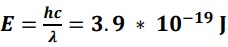 . Assuming a neuron that strongly expresses GCaMP6f under two-photon excitation would emit a very high 10<sup>7</sup>photons per second (Har-Gil et al., 2018), its total emission power would be P = N<sub>photons</sub> * E ≈ 4pW. Assuming this is spread over the surface of the cell (sphere with 10 µm diameter), this translates to
 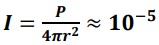 . This is several orders of magnitude below the value of 1 mW/mm<sup>2</sup> irradiance required to activate ChrimsonR modestly at peak absorption, which is 80nm away from GCaMP6f emission (Klapoetke et al., 2014). Note that this would be true even when ChrimsonR is injected at the site of imaging (Vasilevskaya and Keller, 2026).
(4) Incision of the cortex for implantation of a prism is a significant cortical injury that likely induces CSD instantaneously and may change the propensity for CSD in subsequent recordings. Please comment on this limitation and address how much time elapsed after surgery before imaging.
We suspect that the question is driven by a misunderstanding. While it is likely that the implantation triggers a CSD (and likely so does a standard two-photon window implantation), the implantation surgery and the experiments/imaging are separated by at least 3 weeks (Methods). We have never observed spontaneous CSDs in the days and weeks following an implantation surgery.
(5) Method details are missing or insufficiently described for location, titer, and injection strategy for 2-photon experiments.
We have added additional details as requested by the reviewer (Methods).
(6) Given the wide range of parameters used for ECS in mice and ECT in humans, the authors should provide tables for what stimulation parameters were used for each recording. These protocols were chosen manually rather than randomly or systematically, which introduces confounding factors into analyses that use parameters as an independent variable.
We have added two tables (Table S3 and Table S4) that displays the stimulation parameters used for each figure, as well as the distribution of parameters for mice and patients. More importantly, the properties of the travelling calcium event do not depend on the stimulation charge (Figure S3), which removes this confounding factor and supports the idea that the calcium event is a CSD.
(7) While much of the cFOS staining after unilateral CSD shows hemisphere-specific asymmetry, several regions (piriform cortex, amygdala, thalamus) do appear to have bilateral cFOS expression. Please comment on this.
That is correct – only the cortical expression of Fos depends on the cortical CSD (see our reply to comment (1) of reviewer 1). Quantification of the whole-brain Fos expression following ECS is outside the scope of the manuscript, but it is something we are currently pursuing for separate publication. We have now reworked the section describing the Fos expression to make it clear that we are only talking about cortical expression of Fos (Results).
(8) The discussion states: "If CSD accounts for plasticity effects, triggering a CSD in a non-seizure context may be sufficient to elicit therapeutic effects. This is supported by the clinical success of ultra-brief stimulation treatments that do not cause seizures, such as rTMS with accelerated protocols, which achieves treatment efficacy on par with ECT for major depressive disorder". Are the authors implying that TMS induces CSD? What evidence supports this idea?
That was indeed our speculation based on ongoing work on TMS in the lab – but it was poorly phrased and unnecessary. We have rephrased.
(9) This statement - "Assuming psychosis is the result of thalamocortical coupling that is too weak in frontal areas of the cortex" (lines 583-585) - may be overly speculative.
It is speculative indeed – but the speculation is not unfounded and has been made previously. The primary evidence is correlative in that schizophrenia is characterized by a reduction in coupling between thalamus and frontal areas of cortex – see e.g. (Giraldo-Chica and Woodward, 2017; Vinogradov et al., 2023). We have argued in previous work that combining this with computational models of psychosis (Sterzer et al., 2018), it is not unreasonable to speculate that a reduction in the coupling between thalamus and frontal areas of cortex could explain psychosis (Keller and Sterzer, 2024). The value of that speculation here is that it forms a testable hypothesis for the mechanism of action of ECT. Nevertheless, we have rephrased the statement slightly to make it clearer that this is still speculation.
Reviewer #3 (Recommendations for the authors):
The authors should design/execute an experiment(s) to attempt to prove causality between CSD, calcium influx, cFOS expression, and therapeutic effect. At a minimum, the authors need to revise claims regarding novelty, as the manuscript, as written, is misleading to a reader not familiar with the field.
Regarding novelty – see discussion above.
Regarding therapeutic effects – we are in the process of testing this in patients. Using CSD measurements during ECT to test whether CSD is a better predictor of treatment outcome. I suspect that this will, however, require many more labs to come to firm conclusions. Our aim here is to inspire these experiments. That is why we speculate about clinical relevance in the abstract and the discussion.
References
Bahari, F., Ssentongo, P., Liu, J., Kimbugwe, J., Curay, C., Schiff, S.J., Gluckman, B.J., 2020. Seizure-associated spreading depression is a major feature of ictal events in two animal models of chronic epilepsy. https://doi.org/10.1101/455519
Bolhuis, J.J., Hetebrij, E., Den Boer-Visser, A.M., De Groot, J.H., Zijlstra, G.G.O., 2001. Localized immediate early gene expression related to the strength of song learning in socially reared zebra finches. European Journal of Neuroscience 13, 2165–2170. https://doi.org/10.1046/j.0953816x.2001.01588.x
Bonaccini Calia, A., Masvidal-Codina, E., Smith, T.M., Schäfer, N., Rathore, D., Rodríguez-Lucas, E., Illa, X., De la Cruz, J.M., Del Corro, E., Prats-Alfonso, E., Viana, D., Bousquet, J., Hébert, C., Martínez-Aguilar, J., Sperling, J.R., Drummond, M., Halder, A., Dodd, A., Barr, K., Savage, S., Fornell, J., Sort, J., Guger, C., Villa, R., Kostarelos, K., Wykes, R.C., Guimerà-Brunet, A., Garrido, J.A., 2022. Full-bandwidth electrophysiology of seizures and epileptiform activity enabled by flexible graphene microtransistor depth neural probes. Nat. Nanotechnol. 17, 301–309. https://doi.org/10.1038/s41565-021-01041-9
Brumback, R.A., Staton, R.D., 1982. The Electroencephalographic Pattern during Electroconvulsive Therapy. Clinical Electroencephalography 13, 148–153. https://doi.org/10.1177/155005948201300306
Calais, J.B., Valvassori, S.S., Resende, W.R., Feier, G., Athié, M.C.P., Ribeiro, S., Gattaz, W.F., Quevedo, J., Ojopi, E.B., 2013. Long-term decrease in immediate early gene expression after electroconvulsive seizures. J Neural Transm (Vienna) 120, 259–266. https://doi.org/10.1007/s00702-012-0861-4
Chaudhuri, A., Zangenehpour, S., Rahbar-Dehgan, F., Ye, F., 2000. Molecular maps of neural activity and quiescence. Acta Neurobiol Exp (Wars) 60, 403–410. https://doi.org/10.55782/ane-2000-1359
Cohen, S., Greenberg, M.E., 2008. Communication between the synapse and the nucleus in neuronal development, plasticity, and disease. Annu Rev Cell Dev Biol 24, 183–209. https://doi.org/10.1146/annurev.cellbio.24.110707.175235
Cruz, F.C., Javier Rubio, F., Hope, B.T., 2015. Using c-fos to study neuronal ensembles in corticostriatal circuitry of addiction. Brain Res 1628, 157–173. https://doi.org/10.1016/j.brainres.2014.11.005
Davis, S., Vanhoutte, P., Pages, C., Caboche, J., Laroche, S., 2000. The MAPK/ERK cascade targets both Elk-1 and cAMP response element-binding protein to control long-term potentiation-dependent gene expression in the dentate gyrus in vivo. J Neurosci 20, 4563–4572. https://doi.org/10.1523/JNEUROSCI.20-12-04563.2000
de Hoz, L., Gierej, D., Lioudyno, V., Jaworski, J., Blazejczyk, M., Cruces-Solís, H., Beroun, A., Lebitko, T., Nikolaev, T., Knapska, E., Nelken, I., Kaczmarek, L., 2018. Blocking c-Fos Expression Reveals the Role of Auditory Cortex Plasticity in Sound Frequency Discrimination Learning. Cereb Cortex 28, 1645–1655. https://doi.org/10.1093/cercor/bhx060
Dell’Orco, M., Weisend, J.E., Perrone-Bizzozero, N.I., Carlson, A.P., Morton, R.A., Linsenbardt, D.N., Shuttleworth, C.W., 2023. Repetitive spreading depolarization induces gene expression changes related to synaptic plasticity and neuroprotective pathways. Front. Cell. Neurosci. 17. https://doi.org/10.3389/fncel.2023.1292661
Durchdewald, M., Angel, P., Hess, J., 2009. The transcription factor Fos: a Janus-type regulator in health and disease. Histol Histopathol 24, 1451–1461. https://doi.org/10.14670/HH-24.1451
Fields, R.D., Eshete, F., Stevens, B., Itoh, K., 1997. Action potential-dependent regulation of gene expression: temporal specificity in ca2+, cAMP-responsive element-binding proteins, and mitogen-activated protein kinase signaling. J Neurosci 17, 7252–7266. https://doi.org/10.1523/JNEUROSCI.17-19-07252.1997
Fleischmann, A., Hvalby, O., Jensen, V., Strekalova, T., Zacher, C., Layer, L.E., Kvello, A., Reschke, M., Spanagel, R., Sprengel, R., Wagner, E.F., Gass, P., 2003. Impaired Long-Term Memory and NR2AType NMDA Receptor-Dependent Synaptic Plasticity in Mice Lacking c-Fos in the CNS. J. Neurosci. 23, 9116–9122. https://doi.org/10.1523/JNEUROSCI.23-27-09116.2003
Francis-Taylor, R., Ophel, G., Martin, D., Loo, C., 2020. The ictal EEG in ECT: A systematic review of the relationships between ictal features, ECT technique, seizure threshold and outcomes. Brain Stimulation 13, 1644–1654. https://doi.org/10.1016/j.brs.2020.09.009
Giraldo-Chica, M., Woodward, N.D., 2017. Review of thalamocortical resting-state fMRI studies in schizophrenia. Schizophr Res 180, 58–63. https://doi.org/10.1016/j.schres.2016.08.005
Har-Gil, H., Golgher, L., Israel, S., Kain, D., Cheshnovsky, O., Parnas, M., Blinder, P., 2018. PySight: plug and play photon counting for fast continuous volumetric intravital microscopy. Optica 5, 1104. https://doi.org/10.1364/OPTICA.5.001104
Huels, E.R., Kafashan, M., Hickman, L.B., Ching, S., Lin, N., Lenze, E.J., Farber, N.B., Avidan, M.S., Hogan, R.E., Palanca, B.J.A., 2023. Central-positive complexes in ECT-induced seizures: Possible evidence for thalamocortical mechanisms. Clin Neurophysiol 146, 77–86. https://doi.org/10.1016/j.clinph.2022.11.015
Kawai, R., Markman, T., Poddar, R., Ko, R., Fantana, A.L., Dhawale, A.K., Kampff, A.R., Ölveczky, B.P., 2015. Motor cortex is required for learning but not for executing a motor skill. Neuron 86, 800– 812. https://doi.org/10.1016/j.neuron.2015.03.024
Keller, G.B., Sterzer, P., 2024. Predictive Processing: A Circuit Approach to Psychosis. Annu Rev Neurosci 47, 85–101. https://doi.org/10.1146/annurev-neuro-100223-121214
Kimpo, R.R., Doupe, A.J., 1997. FOS Is Induced by Singing in Distinct Neuronal Populations in a Motor Network. Neuron 18, 315–325. https://doi.org/10.1016/S0896-6273(00)80271-8
Klapoetke, N.C., Murata, Y., Kim, S.S., Pulver, S.R., Birdsey-Benson, A., Cho, Y.K., Morimoto, T.K., Chuong, A.S., Carpenter, E.J., Tian, Z., Wang, J., Xie, Y., Yan, Z., Zhang, Y., Chow, B.Y., Surek, B., Melkonian, M., Jayaraman, V., Constantine-Paton, M., Wong, G.K.-S., Boyden, E.S., 2014. Independent optical excitation of distinct neural populations. Nat Methods 11, 338–346. https://doi.org/10.1038/nmeth.2836
Largo, C., Ibarz, J.M., Herreras, O., 1997. Effects of the Gliotoxin Fluorocitrate on Spreading Depression and Glial Membrane Potential in Rat Brain In Situ. Journal of Neurophysiology 78, 295–307. https://doi.org/10.1152/jn.1997.78.1.295
Leao, A.A.P., 1944. Spreading depression of activity in the cerebral cortex. Journal of Neurophysiology 7, 359–390. https://doi.org/10.1152/jn.1944.7.6.359
Mahringer, D., Petersen, A.V., Fiser, A., Okuno, H., Bito, H., Perrier, J.-F., Keller, G.B., 2019. Expression of c-Fos and Arc in hippocampal region CA1 marks neurons that exhibit learning-related activity changes. https://doi.org/10.1101/644526
Mahringer, D., Zmarz, P., Okuno, H., Bito, H., Keller, G.B., 2022. Functional correlates of immediate early gene expression in mouse visual cortex. Peer Community Journal 2. https://doi.org/10.24072/pcjournal.156
Meeren, H.K.M., Pijn, J.P.M., Luijtelaar, E.L.J.M.V., Coenen, A.M.L., Silva, F.H.L. da, 2002. Cortical Focus Drives Widespread Corticothalamic Networks during Spontaneous Absence Seizures in Rats. J. Neurosci. 22, 1480–1495. https://doi.org/10.1523/JNEUROSCI.22-04-01480.2002
Minatohara, K., Akiyoshi, M., Okuno, H., 2015. Role of Immediate-Early Genes in Synaptic Plasticity and Neuronal Ensembles Underlying the Memory Trace. Front Mol Neurosci 8, 78. https://doi.org/10.3389/fnmol.2015.00078
Morgan, J.I., Curran, T., 1991. Stimulus-transcription coupling in the nervous system: involvement of the inducible proto-oncogenes fos and jun. Annu Rev Neurosci 14, 421–451. https://doi.org/10.1146/annurev.ne.14.030191.002225
Morinobu, S., Nibuya, M., Duman, R.S., 1995. Chronic antidepressant treatment down-regulates the induction of c-fos mRNA in response to acute stress in rat frontal cortex. Neuropsychopharmacology 12, 221–228. https://doi.org/10.1016/0893-133X(94)00067-A
Nakadate, K., Imamura, K., Watanabe, Y., 2012. Effects of monocular deprivation on the spatial pattern of visually induced expression of c-Fos protein. Neuroscience 202, 17–28. https://doi.org/10.1016/j.neuroscience.2011.12.004
Pandey, A., Kang, S., Pacchiarini, N., Wyszynska, H., Masseri, Z., O’Neill, J., Honey, R.C., Fox, K., 2026. Secondary Somatosensory Cortex Is Required for Learning but Not Execution of a Tactile Discrimination. Eur J Neurosci 63, e70390. https://doi.org/10.1111/ejn.70390
Park, H.G., Yu, H.S., Park, S., Ahn, Y.M., Kim, Y.S., Kim, S.H., 2014. Repeated treatment with electroconvulsive seizures induces HDAC2 expression and down-regulation of NMDA receptorrelated genes through histone deacetylation in the rat frontal cortex. Int J Neuropsychopharmacol 17, 1487–1500. https://doi.org/10.1017/S1461145714000248
Polack, P.-O., Mahon, S., Chavez, M., Charpier, S., 2009. Inactivation of the Somatosensory Cortex Prevents Paroxysmal Oscillations in Cortical and Related Thalamic Neurons in a Genetic Model of Absence Epilepsy. Cereb Cortex 19, 2078–2091. https://doi.org/10.1093/cercor/bhn237
Rosenthal, Z.P., Majeski, J.B., Somarowthu, A., Quinn, D.K., Lindquist, B.E., Putt, M.E., Karaj, A., Favilla, C.G., Baker, W.B., Hosseini, G., Rodriguez, J.P., Cristancho, M.A., Sheline, Y.I., William Shuttleworth, C., Abbott, C.C., Yodh, A.G., Goldberg, E.M., 2025. Electroconvulsive therapy generates a postictal wave of spreading depolarization in mice and humans. Nat Commun 16, 4619. https://doi.org/10.1038/s41467-025-59900-1
Roy, D.S., Arons, A., Mitchell, T.I., Pignatelli, M., Ryan, T.J., Tonegawa, S., 2016. Memory retrieval by activating engram cells in mouse models of early Alzheimer’s disease. Nature 531, 508–512. https://doi.org/10.1038/nature17172
Ryan, T.J., Roy, D.S., Pignatelli, M., Arons, A., Tonegawa, S., 2015. Memory. Engram cells retain memory under retrograde amnesia. Science 348, 1007–1013. https://doi.org/10.1126/science.aaa5542
Scangos, K.W., Weiner, R.D., Coffey, C.E., Krystal, A.D., 2019. An electrophysiological biomarker that may predict treatment response to ECT. J ECT 35, 95–102. https://doi.org/10.1097/YCT.0000000000000557
Sheng, M., Greenberg, M.E., 1990. The regulation and function of c-fos and other immediate early genes in the nervous system. Neuron 4, 477–485. https://doi.org/10.1016/0896-6273(90)90106-p
Sterzer, P., Adams, R.A., Fletcher, P., Frith, C., Lawrie, S.M., Muckli, L., Petrovic, P., Uhlhaas, P., Voss, M., Corlett, P.R., 2018. The Predictive Coding Account of Psychosis. Biol Psychiatry 84, 634–643. https://doi.org/10.1016/j.biopsych.2018.05.015
Tanaka, K.Z., He, H., Tomar, A., Niisato, K., Huang, A.J.Y., McHugh, T.J., 2018. The hippocampal engram maps experience but not place. Science 361, 392–397. https://doi.org/10.1126/science.aat5397
Tyssowski, K.M., DeStefino, N.R., Cho, J.-H., Dunn, C.J., Poston, R.G., Carty, C.E., Jones, R.D., Chang, S.M., Romeo, P., Wurzelmann, M.K., Ward, J.M., Andermann, M.L., Saha, R.N., Dudek, S.M., Gray, J.M., 2018. Different Neuronal Activity Patterns Induce Different Gene Expression Programs. Neuron 98, 530-546.e11. https://doi.org/10.1016/j.neuron.2018.04.001
Vasilevskaya, A., Keller, G.B., 2026. A functional influence based circuit motif that constrains the set of plausible algorithms of cortical function. eLife 15. https://doi.org/10.7554/eLife.110827.1
Vinogradov, S., Chafee, M.V., Lee, E., Morishita, H., 2023. Psychosis spectrum illnesses as disorders of prefrontal critical period plasticity. Neuropsychopharmacology 48, 168–185. https://doi.org/10.1038/s41386-022-01451-w
Watanabe, Y., Johnson, R.S., Butler, L.S., Binder, D.K., Spiegelman, B.M., Papaioannou, V.E., McNamara, J.O., 1996. Null Mutation of c-fos Impairs Structural and Functional Plasticities in the Kindling Model of Epilepsy. J Neurosci 16, 3827–3836. https://doi.org/10.1523/JNEUROSCI.16-1203827.1996
Wei, Z., Lin, B.-J., Chen, T.-W., Daie, K., Svoboda, K., Druckmann, S., 2020. A comparison of neuronal population dynamics measured with calcium imaging and electrophysiology. PLoS Comput Biol 16, e1008198. https://doi.org/10.1371/journal.pcbi.1008198
Winston, S.M., Hayward, M.D., Nestler, E.J., Duman, R.S., 1990. Chronic electroconvulsive seizures down-regulate expression of the immediate-early genes c-fos and c-jun in rat cerebral cortex. J Neurochem 54, 1920–1925. https://doi.org/10.1111/j.1471-4159.1990.tb04892.x
Xia, Z., Dudek, H., Miranti, C.K., Greenberg, M.E., 1996. Calcium influx via the NMDA receptor induces immediate early gene transcription by a MAP kinase/ERK-dependent mechanism. J Neurosci 16, 5425–5436. https://doi.org/10.1523/JNEUROSCI.16-17-05425.1996
Yap, E.-L., Pettit, N.L., Davis, C.P., Nagy, M.A., Harmin, D.A., Golden, E., Dagliyan, O., Lin, C., Rudolph, S., Sharma, N., Griffith, E.C., Harvey, C.D., Greenberg, M.E., 2021. Bidirectional perisomatic inhibitory plasticity of a Fos neuronal network. Nature 590, 115–121. https://doi.org/10.1038/s41586-020-3031-0
Yassin, L., Benedetti, B.L., Jouhanneau, J.-S., Wen, J.A., Poulet, J.F.A., Barth, A.L., 2010. An embedded subnetwork of highly active neurons in the neocortex. Neuron 68, 1043–1050. https://doi.org/10.1016/j.neuron.2010.11.029