"theres no reason to want it"
"theres no reason to want it"
"theres no reason to want it"
"theres no reason to want it"
"theres no reason to want it"
"theres no reason to want it"
"theres no reason to want it"
"theres no reason to want it"
"theres no reason to want it"
"theres no reason to want it"
"theres no reason to want it"
"theres no reason to want it"
"theres no reason to want it"
"theres no reason to want it"
Main menu


Personal tools
Contents
Astrolabe
Tools
Appearance
Text
Width
Color (beta)
From Wikipedia, the free encyclopedia
For other pages with a similar name, see Astrolabe (disambiguation). Not to be confused with Cosmolabe.
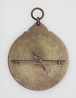
North African, 9th century AD, Planispheric Astrolabe. Khalili Collection.

A modern astrolabe made in Tabriz, Iran in 2013.
An astrolabe (Greek: ἀστρολάβος astrolábos, 'star-taker'; Arabic: ٱلأَسْطُرلاب al-Asṭurlāb; Persian: ستارهیاب Setāreyāb) is an astronomical instrument dating to ancient times. It serves as a star chart and physical model of visible heavenly bodies. Its various functions also make it an elaborate inclinometer and an analog calculation device capable of working out several kinds of problems in astronomy. In its simplest form it is a metal disc with a pattern of wires, cutouts, and perforations that allows a user to calculate astronomical positions precisely. It is able to measure the altitude above the horizon of a celestial body, day or night; it can be used to identify stars or planets, to determine local latitude given local time (and vice versa), to survey, or to triangulate. It was used in classical antiquity, the Islamic Golden Age, the European Middle Ages and the Age of Discovery for all these purposes.
The astrolabe, which is a precursor to the sextant,^[1]^ is effective for determining latitude on land or calm seas. Although it is less reliable on the heaving deck of a ship in rough seas, the mariner's astrolabe was developed to solve that problem.
Applications

16th-century woodcut of measurement of a building's height with an astrolabe
The 10th-century astronomer ʿAbd al-Raḥmān al-Ṣūfī wrote a massive text of 386 chapters on the astrolabe, which reportedly described more than 1,000 applications for the astrolabe's various functions.^[2]^ These ranged from the astrological, the astronomical and the religious, to navigation, seasonal and daily time-keeping, and tide tables. At the time of their use, astrology was widely considered as much of a serious science as astronomy, and study of the two went hand-in-hand. The astronomical interest varied between folk astronomy (of the pre-Islamic tradition in Arabia) which was concerned with celestial and seasonal observations, and mathematical astronomy, which would inform intellectual practices and precise calculations based on astronomical observations. In regard to the astrolabe's religious function, the demands of Islamic prayer times were to be astronomically determined to ensure precise daily timings, and the qibla, the direction of Mecca towards which Muslims must pray, could also be determined by this device. In addition to this, the lunar calendar that was informed by the calculations of the astrolabe was of great significance to the religion of Islam, given that it determines the dates of important religious observances such as Ramadan.^[citation needed]^
Etymology
The Oxford English Dictionary gives the translation "star-taker" for the English word astrolabe and traces it through medieval Latin to the Greek word ἀστρολάβος : astrolábos,^[3]^^[4]^ from ἄστρον : astron "star" and λαμβάνειν : lambanein "to take".^[5]^
In the medieval Islamic world the Arabic word al-Asturlāb (i.e., astrolabe) was given various etymologies. In Arabic texts, the word is translated as ākhidhu al-Nujūm (Arabic: آخِذُ ٱلنُّجُومْ, lit. 'star-taker'), a direct translation of the Greek word.^[6]^
Al-Biruni quotes and criticises medieval scientist Hamza al-Isfahani who stated:^[6]^ "asturlab is an arabisation of this Persian phrase" (sitara yab, meaning "taker of the stars").^[7]^ In medieval Islamic sources, there is also a folk etymology of the word as "lines of lab", where "Lab" refers to a certain son of Idris (Enoch). This etymology is mentioned by a 10th-century scientist named al-Qummi but rejected by al-Khwarizmi.^[8]^
History
Ancient era
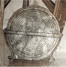
An astrolabe is essentially a plane (two-dimensional) version of an armillary sphere, which had already been invented in the Hellenistic period and probably been used by Hipparchus to produce his star catalogue. Theon of Alexandria (c. 335 -- c. 405) wrote a detailed treatise on the astrolabe.^[9]^ The invention of the plane astrolabe is sometimes wrongly attributed to Theon's daughter Hypatia (born c. 350--370; died AD 415),^[10]^^[11]^^[12]^^[13]^ but it's known to have been used much earlier.^[11]^^[12]^^[13]^ The misattribution comes from a misinterpretation of a statement in a letter written by Hypatia's pupil Synesius (c. 373 -- c. 414),^[11]^^[12]^^[13]^ which mentions that Hypatia had taught him how to construct a plane astrolabe, but does not say that she invented it.^[11]^^[12]^^[13]^ Lewis argues that Ptolemy used an astrolabe to make the astronomical observations recorded in the Tetrabiblos.^[9]^ However, Emilie Savage-Smith notes "there is no convincing evidence that Ptolemy or any of his predecessors knew about the planispheric astrolabe".^[14]^ In chapter 5,1 of the Almagest, Ptolemy describes the construction of an armillary sphere, and it is usually assumed that this was the instrument he used.
Astrolabes continued to be used in the Byzantine Empire. Christian philosopher John Philoponus wrote a treatise (c. 550) on the astrolabe in Greek, which is the earliest extant treatise on the instrument.^[a]^ Mesopotamian bishop Severus Sebokht also wrote a treatise on the astrolabe in the Syriac language during the mid-7th century.^[b]^ Sebokht refers to the astrolabe as being made of brass in the introduction of his treatise, indicating that metal astrolabes were known in the Christian East well before they were developed in the Islamic world or in the Latin West.^[15]^
Medieval era
Astrolabes were further developed in the medieval Islamic world, where Muslim astronomers introduced angular scales to the design,^[16]^ adding circles indicating azimuths on the horizon.^[17]^ It was widely used throughout the Muslim world, chiefly as an aid to navigation and as a way of finding the Qibla, the direction of Mecca. Eighth-century mathematician Muhammad al-Fazari is the first person credited with building the astrolabe in the Islamic world.^[18]^
The mathematical background was established by Muslim astronomer Albatenius in his treatise Kitab az-Zij (c. AD 920), which was translated into Latin by Plato Tiburtinus (De Motu Stellarum). The earliest surviving astrolabe is dated AH 315 (AD 927--928). In the Islamic world, astrolabes were used to find the times of sunrise and the rising of fixed stars, to help schedule morning prayers (salat). In the 10th century, al-Sufi first described over 1,000 different uses of an astrolabe, in areas as diverse as astronomy, astrology, navigation, surveying, timekeeping, prayer, Salat, Qibla, etc.^[19]^^[20]^
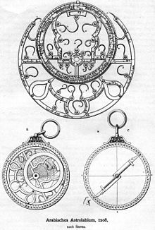
An Arab astrolabe from 1208
The spherical astrolabe was a variation of both the astrolabe and the armillary sphere, invented during the Middle Ages by astronomers and inventors in the Islamic world.^[c]^ The earliest description of the spherical astrolabe dates to Al-Nayrizi (fl. 892--902). In the 12th century, Sharaf al-Dīn al-Tūsī invented the linear astrolabe, sometimes called the "staff of al-Tusi", which was "a simple wooden rod with graduated markings but without sights. It was furnished with a plumb line and a double chord for making angular measurements and bore a perforated pointer".^[21]^ The geared mechanical astrolabe was invented by Abi Bakr of Isfahan in 1235.^[22]^
The first known metal astrolabe in Western Europe is the Destombes astrolabe made from brass in the eleventh century in Portugal.^[23]^^[24]^ Metal astrolabes avoided the warping that large wooden ones were prone to, allowing the construction of larger and therefore more accurate instruments. Metal astrolabes were heavier than wooden instruments of the same size, making it difficult to use them in navigation.^[25]^

Spherical astrolabe

A depiction of Hermann of Reichenau with an astrolabe in a 13th-century manuscript by Matthew Paris
Herman Contractus of Reichenau Abbey, examined the use of the astrolabe in Mensura Astrolai during the 11th century.^[26]^ Peter of Maricourt wrote a treatise on the construction and use of a universal astrolabe in the last half of the 13th century entitled Nova compositio astrolabii particularis. Universal astrolabes can be found at the History of Science Museum in Oxford.^[27]^ David A. King, historian of Islamic instrumentation, describes the universal astrolobe designed by Ibn al-Sarraj of Aleppo (aka Ahmad bin Abi Bakr; fl. 1328) as "the most sophisticated astronomical instrument from the entire Medieval and Renaissance periods".^[28]^
English author Geoffrey Chaucer (c. 1343--1400) compiled A Treatise on the Astrolabe for his son, mainly based on a work by Messahalla or Ibn al-Saffar.^[29]^^[30]^ The same source was translated by French astronomer and astrologer Pélerin de Prusse and others. The first printed book on the astrolabe was Composition and Use of Astrolabe by Christian of Prachatice, also using Messahalla, but relatively original.

Front of an Indian astrolabe now kept at the Royal Museum of Scotland at Edinburgh.
In 1370, the first Indian treatise on the astrolabe was written by the Jain astronomer Mahendra Suri, titled Yantrarāja.^[31]^
A simplified astrolabe, known as a balesilha, was used by sailors to get an accurate reading of latitude while at sea. The use of the balesilha was promoted by Prince Henry (1394--1460) while navigating for Portugal.^[32]^
The astrolabe was almost certainly first brought north of the Pyrenees by Gerbert of Aurillac (future Pope Sylvester II), where it was integrated into the quadrivium at the school in Reims, France, sometime before the turn of the 11th century.^[33]^ In the 15th century, French instrument maker Jean Fusoris (c. 1365--1436) also started remaking and selling astrolabes in his shop in Paris, along with portable sundials and other popular scientific devices of the day.
Astronomical Instrument Detail by Ieremias Palladas 1612
Thirteen of his astrolabes survive to this day.^[34]^ One more special example of craftsmanship in early 15th-century Europe is the astrolabe designed by Antonius de Pacento and made by Dominicus de Lanzano, dated 1420.^[35]^
In the 16th century, Johannes Stöffler published Elucidatio fabricae ususque astrolabii, a manual of the construction and use of the astrolabe. Four identical 16th-century astrolabes made by Georg Hartmann provide some of the earliest evidence for batch production by division of labor. In 1612, Greek painter Ieremias Palladas incorporated a sophisticated astrolabe in his painting depicting Catherine of Alexandria. The painting was entitled Catherine of Alexandria and featured a device called the System of the Universe (Σύστημα τοῦ Παντός). The device featured the planets with the names in Greek: Selene (Moon), Hermes (Mercury), Aphrodite (Venus), Helios (Sun), Ares (Mars), Zeus (Jupiter), and Chronos (Saturn). The device also featured celestial spheres following the Ptolemaic model and Earth was depicted as a blue sphere with circles of geographic coordinates. A complex line representing the axis of the Earth covered the entire instrument.^[36]^
Medieval astrolabes
Astrolabes and clocks
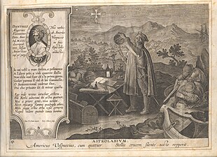
Amerigo Vespucci observing the Southern Cross by looking over the top of an armillary sphere bizarrely held from the top as if it were an astrolabe; however, an astrolabe cannot be used by looking over its top. The page inexplicably contains the word astrolabium. By Jan Collaert II. Museum Plantin-Moretus, Antwerp, Belgium.
Mechanical astronomical clocks were initially influenced by the astrolabe; they could be seen in many ways as clockwork astrolabes designed to produce a continual display of the current position of the sun, stars, and planets. For example, Richard of Wallingford's clock (c. 1330) consisted essentially of a star map rotating behind a fixed rete, similar to that of an astrolabe.^[37]^
Many astronomical clocks use an astrolabe-style display, such as the famous clock at Prague, adopting a stereographic projection (see below) of the ecliptic plane. In recent times, astrolabe watches have become popular. For example, Swiss watchmaker Ludwig Oechslin designed and built an astrolabe wristwatch in conjunction with Ulysse Nardin in 1985.^[38]^ Dutch watchmaker Christaan van der Klauuw also manufactures astrolabe watches today.^[39]^
Construction
An astrolabe consists of a disk, called the mater (mother), which is deep enough to hold one or more flat plates called tympans, or climates. A tympan is made for a specific latitude and is engraved with a stereographic projection of circles denoting azimuth and altitude and representing the portion of the celestial sphere above the local horizon. The rim of the mater is typically graduated into hours of time, degrees of arc, or both.^[40]^
Above the mater and tympan, the rete, a framework bearing a projection of the ecliptic plane and several pointers indicating the positions of the brightest stars, is free to rotate. These pointers are often just simple points, but depending on the skill of the craftsman can be very elaborate and artistic. There are examples of astrolabes with artistic pointers in the shape of balls, stars, snakes, hands, dogs' heads, and leaves, among others.^[40]^ The names of the indicated stars were often engraved on the pointers in Arabic or Latin.^[41]^ Some astrolabes have a narrow rule or label which rotates over the rete, and may be marked with a scale of declinations.
The rete, representing the sky, functions as a star chart. When it is rotated, the stars and the ecliptic move over the projection of the coordinates on the tympan. One complete rotation corresponds to the passage of a day. The astrolabe is, therefore, a predecessor of the modern planisphere.
On the back of the mater, there is often engraved a number of scales that are useful in the astrolabe's various applications. These vary from designer to designer, but might include curves for time conversions, a calendar for converting the day of the month to the sun's position on the ecliptic, trigonometric scales, and graduation of 360 degrees around the back edge. The alidade is attached to the back face. An alidade can be seen in the lower right illustration of the Persian astrolabe above. When the astrolabe is held vertically, the alidade can be rotated and the sun or a star sighted along its length, so that its altitude in degrees can be read ("taken") from the graduated edge of the astrolabe; hence the word's Greek roots: "astron" (ἄστρον) = star + "lab-" (λαβ-) = to take. The alidade had vertical and horizontal cross-hairs which plots locations on an azimuthal ring called an almucantar (altitude-distance circle).
An arm called a radius connects from the center of the astrolabe to the optical axis which is parallel with another arm also called a radius. The other radius contains graduations of altitude and distance measurements.
A shadow square also appears on the back of some astrolabes, developed by Muslim astrologists in the 9th Century, whereas devices of the Ancient Greek tradition featured only altitude scales on the back of the devices.^[42]^ This was used to convert shadow lengths and the altitude of the sun, the uses of which were various from surveying to measuring inaccessible heights.^[43]^
Devices were usually signed by their maker with an inscription appearing on the back of the astrolabe, and if there was a patron of the object, their name would appear inscribed on the front, or in some cases, the name of the reigning sultan or the teacher of the astrolabist has also been found to appear inscribed in this place.^[44]^ The date of the astrolabe's construction was often also signed, which has allowed historians to determine that these devices are the second oldest scientific instrument in the world. The inscriptions on astrolabes also allowed historians to conclude that astronomers tended to make their own astrolabes, but that many were also made to order and kept in stock to sell, suggesting there was some contemporary market for the devices.^[44]^
Construction of astrolabes
-

The Hartmann astrolabe in Yale collection. This instrument shows its rete and rule.
-
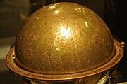
Celestial Globe, Isfahan (?), Iran 1144. Shown at the Louvre Museum, this globe is the third oldest surviving in the world.
-
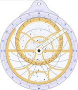
Computer-generated planispheric astrolabe
Mathematical basis
The construction and design of astrolabes are based on the application of the stereographic projection of the celestial sphere. The point from which the projection is usually made is the South Pole. The plane onto which the projection is made is that of the Equator.^[45]^
Designing a tympanum through stereographic projection

Parts of an Astrolabe tympanum
The tympanum captures the celestial coordinate axes upon which the rete will rotate. It is the component that will enable the precise determination of a star's position at a specific time of day and year.
Therefore, it should project:
- The zenith, which will vary depending on the latitude of the astrolabe user.
- The horizon line and almucantar or circles parallel to the horizon, which will allow for the determination of a celestial body's altitude (from the horizon to the zenith).
- The celestial meridian (north-south meridian, passing through the zenith) and secondary meridians (circles intersecting the north-south meridian at the zenith), which will enable the measurement of azimuth for a celestial body.
- The three main circles of latitude (Capricorn, Equator, and Cancer) to determine the exact moments of solstices and equinoxes throughout the year.
The tropics and the equator define the tympanum

Stereographic projection of Earth's tropics and equator from the South Pole.
On the right side of the image above:
- The blue sphere represents the celestial sphere.
- The blue arrow indicates the direction of true north (the North Star).
- The central blue point represents Earth (the observer's location).
- The geographic south of the celestial sphere acts as the projection pole.
- The celestial equatorial plane serves as the projection plane.
- Three parallel circles represent the projection on the celestial sphere of Earth's main circles of latitude:
When projecting onto the celestial equatorial plane, three concentric circles correspond to the celestial sphere's three circles of latitude (left side of the image). The largest of these, the projection on the celestial equatorial plane of the celestial Tropic of Capricorn, defines the size of the astrolabe's tympanum. The center of the tympanum (and the center of the three circles) is actually the north-south axis around which Earth rotates, and therefore, the rete of the astrolabe will rotate around this point as the hours of the day pass (due to Earth's rotational motion).
The three concentric circles on the tympanum are useful for determining the exact moments of solstices and equinoxes throughout the year: if the sun's altitude at noon on the rete is known and coincides with the outer circle of the tympanum (Tropic of Capricorn), it signifies the winter solstice (the sun will be at the zenith for an observer at the Tropic of Capricorn, meaning summer in the southern hemisphere and winter in the northern hemisphere). If, on the other hand, its altitude coincides with the inner circle (Tropic of Cancer), it indicates the summer solstice. If its altitude is on the middle circle (equator), it corresponds to one of the two equinoxes.
The horizon and the measurement of altitude

Stereographic projection of an observer's horizon at a specific latitude
On the right side of the image above:
- The blue arrow indicates the direction of true north (the North Star).
- The central blue point represents Earth (the observer's location).
- The black arrow represents the zenith direction for the observer (which would vary depending on the observer's latitude).
- The two black circles represent the horizon surrounding the observer, which is perpendicular to the zenith vector and defines the portion of the celestial sphere visible to the observer, and its projection on the celestial equatorial plane.
- The geographic south of the celestial sphere acts as the projection pole.
- The celestial equatorial plane serves as the projection plane.
When projecting the horizon onto the celestial equatorial plane, it transforms into an ellipse upward-shifted relatively to the center of the tympanum (both the observer and the projection of the north-south axis). This implies that a portion of the celestial sphere will fall outside the outer circle of the tympanum (the projection of the celestial Tropic of Capricorn) and, therefore, won't be represented.
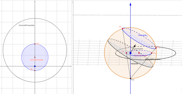
Stereographic projection of the horizon and an almucantar.
Additionally, when drawing circles parallel to the horizon up to the zenith (almucantar), and projecting them on the celestial equatorial plane, as in the image above, a grid of consecutive ellipses is constructed, allowing for the determination of a star's altitude when its rete overlaps with the designed tympanum.
The meridians and the measurement of azimuth

Stereographic projection of the north-south meridian and a meridian 40° E on the tympanum of an astrolabe
On the right side of the image above:
- The blue arrow indicates the direction of true north (the North Star).
- The central blue point represents Earth (the observer's location).
- The black arrow represents the zenith direction for the observer (which would vary depending on the observer's latitude).
- The two black circles represent the horizon surrounding the observer, which is perpendicular to the zenith vector and defines the portion of the celestial sphere visible to the observer, and its projection on the celestial equatorial plane.
- The five red dots represent the zenith, the nadir (the point on the celestial sphere opposite the zenith with respect to the observer), their projections on the celestial equatorial plane, and the center (with no physical meaning attached) of the circle obtained by projecting the secondary meridian (see below) on the celestial equatorial plane.
- The orange circle represents the celestial meridian (or meridian that goes, for the observer, from the north of the horizon to the south of the horizon passing through the zenith).
- The two red circles represent a secondary meridian with an azimuth of 40° East relative to the observer's horizon (which, like all secondary meridians, intersects the principal meridian at the zenith and nadir), and its projection on the celestial equatorial plane.
- The geographic south of the celestial sphere acts as the projection pole.
- The celestial equatorial plane serves as the projection plane.
When projecting the celestial meridian, it results in a straight line that overlaps with the vertical axis of the tympanum, where the zenith and nadir are located. However, when projecting the 40° E meridian, another circle is obtained that passes through both the zenith and nadir projections, so its center is located on the perpendicular bisection of the segment connecting both points. In deed, the projection of the celestial meridian can be considered as a circle with an infinite radius (a straight line) whose center is on this bisection and at an infinite distance from these two points.
If successive meridians that divide the celestial sphere into equal sectors (like "orange slices" radiating from the zenith) are projected, a family of curves passing through the zenith projection on the tympanum is obtained. These curves, once overlaid with the rete containing the major stars, allow for determining the azimuth of a star located on the rete and rotated for a specific time of day.
See also
References
Footnotes
1.
- Savage-Smith, Emilie (1993). "Book Reviews". Journal of Islamic Studies. 4 (2): 296--299. doi:10.1093/jis/4.2.296. There is no evidence for the Hellenistic origin of the spherical astrolabe, but rather evidence so far available suggests that it may have been an early but distinctly Islamic development with no Greek antecedents.
Notes
1.
- Gentili, Graziano; Simonutti, Luisa; Struppa, Daniele C. (2020). "The Mathematics of the Astrolabe and Its History". Journal of Humanistic Mathematics. 10: 101--144. doi:10.5642/jhummath.202001.07. hdl:2158/1182616. S2CID 211008813.
Bibliography
- Evans, James (1998), The History and Practice of Ancient Astronomy, Oxford University Press, ISBN 0-19-509539-1
- Stöffler, Johannes (2007) [First published 1513], Stoeffler's Elucidatio -- The Construction and Use of the Astrolabe [Elucidatio Fabricae Ususque Astrolabii], translated by Gunella, Alessandro; Lamprey, John, John Lamprey, ISBN 978-1-4243-3502-2
- King, D. A. (1981), "The Origin of the Astrolabe According to the Medieval Islamic Sources", Journal for the History of Arabic Science, 5: 43--83
- King, Henry (1978), Geared to the Stars: the Evolution of Planetariums, Orreries, and Astronomical Clocks, University of Toronto Press, ISBN 978-0-8020-2312-4
- Krebs, Robert E.; Krebs, Carolyn A. (2003), Groundbreaking Scientific Experiments, Inventions, and Discoveries of the Ancient World, Greenwood Press, ISBN 978-0-313-31342-4
- Laird, Edgar (1997), Carol Poster and Richard Utz (ed.), "Astrolabes and the Construction of Time in the Late Middle Ages", Constructions of Time in the Late Middle Ages, Evanston, Illinois: Northwestern University Press: 51--69
- Laird, Edgar; Fischer, Robert, eds. (1995), "Critical edition of Pélerin de Prusse on the Astrolabe (translation of Practique de Astralabe)", Medieval & Renaissance Texts & Studies, Binghamton, New York, ISBN 0-86698-132-2
- Lewis, M. J. T. (2001), Surveying Instruments of Greece and Rome, Cambridge University Press, ISBN 978-0-511-48303-5
- Morrison, James E. (2007), The Astrolabe, Janus, ISBN 978-0-939320-30-1
- Neugebauer, Otto E. (1975), A History of Ancient Mathematical Astronomy, Springer, ISBN 978-3-642-61912-0
- North, John David (2005), God's Clockmaker: Richard of Wallingford and the Invention of Time, Continuum International Publishing Group, ISBN 978-1-85285-451-5
External links

Wikimedia Commons has media related to:\
Astrolabe (category)

Wikisource has the text of the 1911 Encyclopædia Britannica article "Astrolabe".

Look up astrolabe in Wiktionary, the free dictionary.
|\
|
|
Astronomy in the medieval Islamic world
|
|\
|
|
Ancient Greek astronomy
|
Portals:
|\
|
|
Authority control databases 
|
Categories:
- Analog computers
- Ancient Greek astronomy
- Ancient Greek technology
- Astrometry
- Astronomical instruments
- Astronomy in the medieval Islamic world
- Greek inventions
- Historical scientific instruments
- Inclinometers
- Marine navigation
- Mechanical calculators
- Navigational equipment
- Technology in the medieval Islamic world
-
Scientific equipment
-
This page was last edited on 26 October 2024, at 23:35 (UTC).
-
Text is available under the Creative Commons Attribution-ShareAlike 4.0 License; additional terms may apply. By using this site, you agree to the Terms of Use and Privacy Policy. Wikipedia® is a registered trademark of the Wikimedia Foundation, Inc., a non-profit organization.
-
Privacy policy
- About Wikipedia
- Disclaimers
- Contact Wikipedia
- Code of Conduct
- Developers
- Statistics
- Cookie statement
-
Mobile view
-

-

-
[
(Top)
](https://en.wikipedia.org/wiki/Astrolabe#)- [
Applications
](https://en.wikipedia.org/wiki/Astrolabe#Applications)- [
Etymology
](https://en.wikipedia.org/wiki/Astrolabe#Etymology)- [
History
](https://en.wikipedia.org/wiki/Astrolabe#History)- - [
Ancient era

](https://en.wikipedia.org/wiki/Astrolabe#Ancient_era)
Construction
](https://en.wikipedia.org/wiki/Astrolabe#Construction)- [
Mathematical basis
](https://en.wikipedia.org/wiki/Astrolabe#Mathematical_basis)- Modern editions of John Philoponus' treatise on the astrolabe are De usu astrolabii eiusque constructione libellus (On the Use and Construction of the Astrolabe), ed. Heinrich Hase, Bonn: E. Weber, 1839, OCLC 165707441 (or id. Rheinisches Museum für Philologie 6 (1839): 127--71); repr. and translated into French by Alain Philippe Segonds, Jean Philopon, traité de l'astrolabe, Paris: Librairie Alain Brieux, 1981, OCLC 10467740; and translated into English by H.W. Green in R.T. Gunther, The Astrolabes of the World, Vol. 1/2, Oxford, 1932, OL 18840299M repr. London: Holland Press, 1976, OL 14132393M pp. 61--81.- O'Leary, De Lacy (1948). How Greek Science Passed to the Arabs. Routledge and Kegan Paul. "The most distinguished Syriac scholar of this later period was Severus Sebokht (d. 666--7), Bishop of Kennesrin. [...] In addition to these works [...] he also wrote on astronomical subjects (Brit. Mus. Add. 14538), and composed a treatise on the astronomical instrument known as the astrolabe, which has been edited and published by F. Nau (Paris, 1899)."\
Severus' treatise was translated by Jessie Payne Smith Margoliouth in R.T. Gunther, Astrolabes of the World, Oxford, 1932, pp. 82--103.- "HISTORIANS' HOME YIELDS RICH LODE; New York Society Searches Its Own Building for Items to Mark Anniversary; SHOW OPENS THURSDAY; Portrait of Stuyvesant and Champlain's Astrolabe Will Be on Display". The New York Times. May 18, 1964. Retrieved February 4, 2024.- Bean, Adam L. (2009). "Astrolabes". In Birx, H. James (ed.). Encyclopedia of Time: Science, Philosophy, Theology, & Culture. Vol. 1. SAGE. pp. 59--60. ISBN 978-1-4129-4164-8.- "Astrolabe". Oxford English Dictionary (2nd ed.). 1989.- "Astrolabe". Oxford Dictionaries. Archived from the original on October 22, 2013.- "Online Etymology Dictionary". Etymonline.com. Retrieved 2013-11-07.- King 1981, p. 44.- King 1981, p. 51.- King 1981, p. 45.- Lewis 2001.- Michael Deakin (August 3, 1997). "Ockham's Razor: Hypatia of Alexandria". ABC Radio. Retrieved July 10, 2014.- Theodore, Jonathan (2016). The Modern Cultural Myth of the Decline and Fall of the Roman Empire. Manchester, England: Palgrave, Macmillan. p. 183. ISBN 978-1-137-56997-4.- Deakin, Michael A. B. (2007). Hypatia of Alexandria: Mathematician and Martyr. Amherst, New York: Prometheus Books. pp. 102--104. ISBN 978-1-59102-520-7.- Bradley, Michael John (2006). The Birth of Mathematics: Ancient Times to 1300. New York City, New York: Infobase Publishing. p. 63. ISBN 9780816054237.- Savage-Smith, Emilie (1992). "Celestial Mapping" (PDF). In Harley, J. B.; Woodward, David (eds.). The History of Cartography, Volume 2, Book 1: Cartography in the Traditional Islamic and South Asian Societies. The History of Cartography. Vol. 2. Chicago, Illinois: University of Chicago Press. ISBN 0226316351.- Sebokht, Severus. "Description of the astrolabe". Tertullian.org.- See p. 289 of Martin, L. C. (1923), "Surveying and navigational instruments from the historical standpoint", Transactions of the Optical Society, 24 (5): 289--303, Bibcode:1923TrOS...24..289M, doi:10.1088/1475-4878/24/5/302, ISSN 1475-4878.- Berggren, J. Lennart (2007), "Mathematics in Medieval Islam", in Katz, Victor J. (ed.), The Mathematics of Egypt, Mesopotamia, China, India, and Islam: a Sourcebook, Princeton University Press, p. 519, ISBN 978-0-691-11485-9- Richard Nelson Frye: Golden Age of Persia. p. 163- Nizamoglu, Cem (2005-08-10). "Using an Astrolabe". Muslim Heritage. Retrieved 2023-10-16.- Lachièz-Rey, Marc; Luminet, Jean-Pierre (2001). Celestial Treasury: From the Music of Spheres to the Conquest of Space. Translated by Joe Laredo. Cambridge, United Kingdom: Cambridge University Press. p. 74. ISBN 978-0-521-80040-2.- O'Connor, John J.; Robertson, Edmund F., "Sharaf al-Din al-Muzaffar al-Tusi", MacTutor History of Mathematics Archive, University of St Andrews- Bedini, Silvio A.; Maddison, Francis R. (1966). "Mechanical Universe: The Astrarium of Giovanni de' Dondi". Transactions of the American Philosophical Society. 56 (5): 1--69. doi:10.2307/1006002. JSTOR 1006002.- "Qantara -- 'Carolingian' astrolabe". Qantara-med.org. Retrieved 2013-11-07.- Nancy Marie Brown (2010), "The Abacus and the Cross". p. 140. Basic Books. ISBN 978-0-465-00950-3- Boyle, David (2011). Toward the Setting Sun: Columbus, Cabot, Vespucci, and the Race for America. Bloomsbury Publishing USA. p. 253. ISBN 9780802779786..- Northrup, Cynthia Clark, ed. (2015). Encyclopedia of world trade: from ancient times to the present (Enhanced Credo ed.). Armonk, New York: Routledge. pp. 72. ISBN 978-0765680587. OCLC 889717964.- "Introduction". The Astrolabe: an Online Resource. 2006. Retrieved 2020-05-15.- Harley, J. B.; Woodward, David (1992). The history of cartography. Chicago, Illinois: University of Chicago Press. p. 31. ISBN 0-226-31635-1.- Kunitzsch, Paul (1981). "On the authenticity of the treatise on the composition and use of the astrolabe ascribed to Messahalla". Archives Internationales d'Histoire des Sciences Oxford. 31 (106): 42--62.- Selin, Helaine (2008-03-12). Encyclopaedia of the History of Science, Technology, and Medicine in Non-Western Cultures. Springer Science & Business Media. p. 1335. ISBN 978-1-4020-4559-2. Paul Kunitzsch has recently established that the Latin treatise on the astrolabe long ascribed to Ma'sh'allah and translated by John of Seville is in fact by Ibn al-Saffar, a disciple of Maslama al-Majriti.- Glick, Thomas; et al., eds. (2005), Medieval Science, Technology, and Medicine: An Encyclopedia, Routledge, p. 464, ISBN 0-415-96930-1- Northrup, Cynthia Clark, ed. (2015). Encyclopedia of world trade : from ancient times to the present ([Enhanced Credo edition] ed.). Armonk, New York: Routledge. pp. 460. ISBN 978-0765680587. OCLC 889717964.- Nancy Marie Brown (2010), "The Abacus and the Cross". p. 143. basic Books. ISBN 978-0-465-00950-3- Hockey, Thomas (2009). The Biographical Encyclopedia of Astronomers. Springer Publishing. ISBN 978-0-387-31022-0. Retrieved August 22, 2012.- Ralf Kern (2010), Wissenschaftliche Instrumente in ihrer Zeit. Band 1: Vom Astrolab zum mathematischen Besteck. Cologne, S. 204. ISBN 978-3-86560-865-9- Vafea, Flora (2017). "The Astronomical Instruments in Saint Catherine's Iconography at the Holy Monastery of Sinai The Almagest Volume 8, Issue 2". Almagest. 8 (2). Paris: University of Paris: 87. doi:10.1484/J.ALMAGEST.5.114932.- North 2005.- "Astrolabium G. Galilei". Ulysse Nardin. Archived from the original on 2 January 2011.- "Christaan van der Klauuw".- Stephenson, Bruce; Bolt, Marvin; Friedman, Anna Felicity (2000). The Universe Unveiled: Instruments and Images through History. Cambridge, UK: Cambridge University Press. pp. 108--109. ISBN 0-521-79143-X.- "Star Names on Astrolabes". Ian Ridpath. Retrieved 2016-11-12.- King, David A. Some Medieval Astronomical Instruments and Their Secrets, in Mazzolini, R. G. (ed.), Non-Verbal Communication in Science prior to 1900. Florence. p. 30.- King, David A. (2018). The Astrolabe: What it is & what it is not. Frankfurt, Germany: Frankfurt.- Mayer, L. A. (1956). Islamic astrolabists and their works*. A. Kunding. Bibcode:[1956iatw.book.....M](https://ui.a
Main menu
Wikipedia The Free Encyclopedia
Donate

Create account
Log in
Personal tools
Contents
(Top)
Navigational sextants
Design
Taking a sight
Adjustment
See also
Notes
References
External links
Sextant
Article
Talk

Read
Edit
View history
Tools
Appearance
Text
Small
Standard
Large
Width
Standard
Wide
Color (beta)
Automatic
Light
Dark
From Wikipedia, the free encyclopedia
This article is about the sextant as used for navigation. For other uses, see Sextant (disambiguation).
Not to be confused with Sexton (disambiguation).
A sextant
A sextant is a doubly reflecting navigation instrument that measures the angular distance between two visible objects. The primary use of a sextant is to measure the angle between an astronomical object and the horizon for the purposes of celestial navigation.
The estimation of this angle, the altitude, is known as sighting or shooting the object, or taking a sight. The angle, and the time when it was measured, can be used to calculate a position line on a nautical or aeronautical chart—for example, sighting the Sun at noon or Polaris at night (in the Northern Hemisphere) to estimate latitude (with sight reduction). Sighting the height of a landmark can give a measure of distance off and, held horizontally, a sextant can measure angles between objects for a position on a chart.[1] A sextant can also be used to measure the lunar distance between the moon and another celestial object (such as a star or planet) in order to determine Greenwich Mean Time and hence longitude.
The principle of the instrument was first implemented around 1731 by John Hadley (1682–1744) and Thomas Godfrey (1704–1749), but it was also found later in the unpublished writings of Isaac Newton (1643–1727).
In 1922, it was modified for aeronautical navigation by Portuguese navigator and naval officer Gago Coutinho.
Navigational sextants
Like the Davis quadrant, the sextant allows celestial objects to be measured relative to the horizon, rather than relative to the instrument. This allows excellent precision. Also, unlike the backstaff, the sextant allows direct observations of stars. This permits the use of the sextant at night when a backstaff is difficult to use. For solar observations, filters allow direct observation of the Sun.
Since the measurement is relative to the horizon, the measuring pointer is a beam of light that reaches to the horizon. The measurement is thus limited by the angular accuracy of the instrument and not the sine error of the length of an alidade, as it is in a mariner's astrolabe or similar older instrument.
A sextant does not require a completely steady aim, because it measures a relative angle. For example, when a sextant is used on a moving ship, the image of both horizon and celestial object will move around in the field of view. However, the relative position of the two images will remain steady, and as long as the user can determine when the celestial object touches the horizon, the accuracy of the measurement will remain high compared to the magnitude of the movement.
The sextant is not dependent upon electricity (unlike many forms of modern navigation) or any human-controlled signals (such as GPS). For these reasons it is considered to be an eminently practical back-up navigation tool for ships.
Design
The frame of a sextant is in the shape of a sector which is approximately 1⁄6 of a circle (60°),[2] hence its name (sextāns, sextantis is the Latin word for "one sixth"). Both smaller and larger instruments are (or were) in use: the octant, quintant (or pentant) and the (doubly reflecting) quadrant[3] span sectors of approximately 1⁄8 of a circle (45°), 1⁄5 of a circle (72°) and 1⁄4 of a circle (90°), respectively. All of these instruments may be termed "sextants".
Marine sextant
Using the sextant to measure the altitude of the Sun above the horizon
Sextants can also be used by navigators to measure horizontal angles between objects.
Attached to the frame are the "horizon mirror", an index arm which moves the index mirror, a sighting telescope, Sun shades, a graduated scale and a micrometer drum gauge for accurate measurements. The scale must be graduated so that the marked degree divisions register twice the angle through which the index arm turns. The scales of the octant, sextant, quintant and quadrant are graduated from below zero to 90°, 120°, 140° and 180° respectively. For example, the sextant illustrated has a scale graduated from −10° to 142°, which is basically a quintant: the frame is a sector of a circle subtending an angle of 76° at the pivot of the index arm.
The necessity for the doubled scale reading follows from consideration of the relations of the fixed ray (between the mirrors), the object ray (from the sighted object) and the direction of the normal perpendicular to the index mirror. When the index arm moves by an angle, say 20°, the angle between the fixed ray and the normal also increases by 20°. But the angle of incidence equals the angle of reflection so the angle between the object ray and the normal must also increase by 20°. The angle between the fixed ray and the object ray must therefore increase by 40°. This is the case shown in the graphic.
There are two types of horizon mirrors on the market today. Both types give good results.
Traditional sextants have a half-horizon mirror, which divides the field of view in two. On one side, there is a view of the horizon; on the other side, a view of the celestial object. The advantage of this type is that both the horizon and celestial object are bright and as clear as possible. This is superior at night and in haze, when the horizon and/or a star being sighted can be difficult to see. However, one has to sweep the celestial object to ensure that the lowest limb of the celestial object touches the horizon.
Whole-horizon sextants use a half-silvered horizon mirror to provide a full view of the horizon. This makes it easy to see when the bottom limb of a celestial object touches the horizon. Since most sights are of the Sun or Moon, and haze is rare without overcast, the low-light advantages of the half-horizon mirror are rarely important in practice.
In both types, larger mirrors give a larger field of view, and thus make it easier to find a celestial object. Modern sextants often have 5 cm or larger mirrors, while 19th-century sextants rarely had a mirror larger than 2.5 cm (one inch). In large part, this is because precision flat mirrors have grown less expensive to manufacture and to silver.
An artificial horizon is useful when the horizon is invisible, as occurs in fog, on moonless nights, in a calm, when sighting through a window or on land surrounded by trees or buildings. There are two common designs of artificial horizon. An artificial horizon can consist simply of a pool of water shielded from the wind, allowing the user to measure the distance between the body and its reflection, and divide by two. Another design allows the mounting of a fluid-filled tube with bubble directly to the sextant.
Most sextants also have filters for use when viewing the Sun and reducing the effects of haze. The filters usually consist of a series of progressively darker glasses that can be used singly or in combination to reduce haze and the Sun's brightness. However, sextants with adjustable polarizing filters have also been manufactured, where the degree of darkness is adjusted by twisting the frame of the filter.
Most sextants mount a 1 or 3-power monocular for viewing. Many users prefer a simple sighting tube, which has a wider, brighter field of view and is easier to use at night. Some navigators mount a light-amplifying monocular to help see the horizon on moonless nights. Others prefer to use a lit artificial horizon.[citation needed]
Professional sextants use a click-stop degree measure and a worm adjustment that reads to a minute, 1/60 of a degree. Most sextants also include a vernier on the worm dial that reads to 0.1 minute. Since 1 minute of error is about a nautical mile, the best possible accuracy of celestial navigation is about 0.1 nautical miles (190 m). At sea, results within several nautical miles, well within visual range, are acceptable. A highly skilled and experienced navigator can determine position to an accuracy of about 0.25-nautical-mile (460 m).[4]
A change in temperature can warp the arc, creating inaccuracies. Many navigators purchase weatherproof cases so that their sextant can be placed outside the cabin to come to equilibrium with outside temperatures. The standard frame designs (see illustration) are supposed to equalise differential angular error from temperature changes. The handle is separated from the arc and frame so that body heat does not warp the frame. Sextants for tropical use are often painted white to reflect sunlight and remain relatively cool. High-precision sextants have an invar (a special low-expansion steel) frame and arc. Some scientific sextants have been constructed of quartz or ceramics with even lower expansions. Many commercial sextants use low-expansion brass or aluminium. Brass is lower-expansion than aluminium, but aluminium sextants are lighter and less tiring to use. Some say they are more accurate because one's hand trembles less. Solid brass frame sextants are less susceptible to wobbling in high winds or when the vessel is working in heavy seas, but as noted are substantially heavier. Sextants with aluminum frames and brass arcs have also been manufactured. Essentially, a sextant is intensely personal to each navigator, and they will choose whichever model has the features which suit them best.
Aircraft sextants are now out of production, but had special features. Most had artificial horizons to permit taking a sight through a flush overhead window. Some also had mechanical averagers to make hundreds of measurements per sight for compensation of random accelerations in the artificial horizon's fluid. Older aircraft sextants had two visual paths, one standard and the other designed for use in open-cockpit aircraft that let one view from directly over the sextant in one's lap. More modern aircraft sextants were periscopic with only a small projection above the fuselage. With these, the navigator pre-computed their sight and then noted the difference in observed versus predicted height of the body to determine their position.
Taking a sight
A sight (or measure) of the angle between the Sun, a star, or a planet, and the horizon is done with the 'star telescope' fitted to the sextant using a visible horizon. On a vessel at sea even on misty days a sight may be done from a low height above the water to give a more definite, better horizon. Navigators hold the sextant by its handle in the right hand, avoiding touching the arc with the fingers.[5]
For a Sun sight, a filter is used to overcome the glare such as "shades" covering both index mirror and the horizon mirror designed to prevent eye damage. Initially, with the index bar set to zero and the shades covering both mirrors, the sextant is aimed at the sun until it can be viewed on both mirrors through the telescope, then lowered vertically until the portion of the horizon directly below it is viewed on both mirrors. It is necessary to flip back the horizon mirror shade to be able to see the horizon more clearly on it. Releasing the index bar (either by releasing a clamping screw, or on modern instruments, using the quick-release button), and moving it towards higher values of the scale, eventually the image of the Sun will reappear on the index mirror and can be aligned to about the level of the horizon on the horizon mirror. Then the fine adjustment screw on the end of the index bar is turned until the bottom curve (the lower limb) of the Sun just touches the horizon. "Swinging" the sextant about the axis of the telescope ensures that the reading is being taken with the instrument held vertically. The angle of the sight is then read from the scale on the arc, making use of the micrometer or vernier scale provided. The exact time of the sight must also be noted simultaneously, and the height of the eye above sea-level recorded.[5]
An alternative method is to estimate the current altitude (angle) of the Sun from navigation tables, then set the index bar to that angle on the arc, apply suitable shades only to the index mirror, and point the instrument directly at the horizon, sweeping it from side to side until a flash of the Sun's rays are seen in the telescope. Fine adjustments are then made as above. This method is less likely to be successful for sighting stars and planets.[5]
Star and planet sights are normally taken during nautical twilight at dawn or dusk, while both the heavenly bodies and the sea horizon are visible. There is no need to use shades or to distinguish the lower limb as the body appears as a mere point in the telescope. The Moon can be sighted, but it appears to move very fast, appears to have different sizes at different times, and sometimes only the lower or upper limb can be distinguished due to its phase.[5]
After a sight is taken, it is reduced to a position by looking at several mathematical procedures. The simplest sight reduction is to draw the equal-altitude circle of the sighted celestial object on a globe. The intersection of that circle with a dead-reckoning track, or another sighting, gives a more precise location.
Sextants can be used very accurately to measure other visible angles, for example between one heavenly body and another and between landmarks ashore. Used horizontally, a sextant can measure the apparent angle between two landmarks such as a lighthouse and a church spire, which can then be used to find the distance off or out to sea (provided the distance between the two landmarks is known). Used vertically, a measurement of the angle between the lantern of a lighthouse of known height and the sea level at its base can also be used for distance off.[5]
Adjustment
Due to the sensitivity of the instrument it is easy to knock the mirrors out of adjustment. For this reason a sextant should be checked frequently for errors and adjusted accordingly.
There are four errors that can be adjusted by the navigator, and they should be removed in the following order.
Perpendicularity error
This is when the index mirror is not perpendicular to the frame of the sextant. To test for this, place the index arm at about 60° on the arc and hold the sextant horizontally with the arc away from you at arm's length and look into the index mirror. The arc of the sextant should appear to continue unbroken into the mirror. If there is an error, then the two views will appear to be broken. Adjust the mirror until the reflection and direct view of the arc appear to be continuous.
Side error
This occurs when the horizon glass/mirror is not perpendicular to the plane of the instrument. To test for this, first zero the index arm then observe a star through the sextant. Then rotate the tangent screw back and forth so that the reflected image passes alternately above and below the direct view. If in changing from one position to another, the reflected image passes directly over the unreflected image, no side error exists. If it passes to one side, side error exists. Alternatively, the user can hold the sextant on its side and observe the horizon to check the sextant during the day. If there are two horizons there is side error. In both cases, adjust the horizon glass/mirror until respectively the star or the horizon dual images merge into one. Side error is generally inconsequential for observations and can be ignored or reduced to a level that is merely inconvenient.
Collimation error
This is when the telescope or monocular is not parallel to the plane of the sextant. To check for this you need to observe two stars 90° or more apart. Bring the two stars into coincidence either to the left or the right of the field of view. Move the sextant slightly so that the stars move to the other side of the field of view. If they separate there is collimation error. As modern sextants rarely use adjustable telescopes, they do not need to be corrected for collimation error.
Index error
This occurs when the index and horizon mirrors are not parallel to each other when the index arm is set to zero. To test for index error, zero the index arm and observe the horizon. If the reflected and direct image of the horizon are in line there is no index error. If one is above the other adjust the index mirror until the two horizons merge. Alternatively, the same procedure can be done at night using a star or the Moon instead of the horizon.
See also
Astrolabe
Bris sextant
Davis quadrant
Gago Coutinho
Harold Gatty
History of longitude
Intercept method
Latitude
Longitude
Longitude by chronometer
Mariner's astrolabe
Navigation
Octant (instrument)
Quadrant (instrument)
Sextant (astronomy)
Notes
Seddon, J. Carl (June 1968). "Line of Position from a Horizontal Angle". Journal of Navigation. 21 (3): 367–369. doi:10.1017/S0373463300024838. ISSN 1469-7785.
A.), McPhee, John (John; NSW., Museums and Galleries (2008). Great Collections : treasures from Art Gallery of NSW, Australian Museum, Botanic Gardens Trust, Historic Houses Trust of NSW, Museum of Contemporary Art, Powerhouse Museum, State Library of NSW, State Records NSW. Museums & Galleries NSW. p. 56. ISBN 9780646496030. OCLC 302147838.
This article treats the doubly reflecting quadrant, not its predecessor described at quadrant.
Dutton's Navigation and Piloting, 12th edition. G.D. Dunlap and H.H. Shufeldt, eds. Naval Institute Press 1972, ISBN 0-87021-163-3
Dixon, Conrad (1968). "5. Using the sextant". Basic Astro Navigation. Adlard Coles. ISBN 0-229-11740-6.
References
Bowditch, Nathaniel (2002). The American Practical Navigator. Bethesda, MD: National Imagery and Mapping Agency. ISBN 0-939837-54-4. Archived from the original on 2007-06-24.
Chisholm, Hugh, ed. (1911). "Sextant" . Encyclopædia Britannica. Vol. 24 (11th ed.). Cambridge University Press. pp. 765–767.
Cutler, Thomas J. (December 2003). Dutton's Nautical Navigation (15th ed.). Annapolis, MD: Naval Institute Press. ISBN 978-1-55750-248-3.
Department of the Air Force (March 2001). Air Navigation (PDF). Department of the Air Force. Retrieved 2014-12-28.
Great Britain Ministry of Defence (Navy) (1995). Admiralty Manual of Seamanship. The Stationery Office. ISBN 0-11-772696-6.
Maloney, Elbert S. (December 2003). Chapman Piloting and Seamanship (64th ed.). New York: Hearst Communications. ISBN 1-58816-089-0.
Martin, William Robert (1911). "Navigation" . In Chisholm, Hugh (ed.). Encyclopædia Britannica. Vol. 19 (11th ed.). Cambridge University Press. pp. 284–298.
External links
Look up sextant in Wiktionary, the free dictionary.
Wikimedia Commons has media related to Sextant.
Her Majesty's Nautical Almanac Office Archived 2011-02-21 at the Wayback Machine
The History of HM Nautical Almanac Office Archived 2016-06-24 at the Wayback Machine
Chapter 17 from the online edition of Nathaniel Bowditch's American Practical Navigator
Understand difference in Antique & Replica Sextant Archived 2017-08-17 at the Wayback Machine
CD-Sextant - Build your own sextant Simple do-it-yourself project.
Lunars web site. online calculation
Complete celnav theory book, including Lunars
Portals:
Earth sciences
Astronomy
icon Stars
Spaceflight
icon Science
Authority control databases Edit this at Wikidata
National
GermanyUnited StatesFranceBnF dataIsrael
Other
NARA
Categories:
Navigational equipmentCelestial navigation1731 introductionsAstronomical instrumentsAngle measuring instruments

This page was last edited on 28 June 2024, at 10:00 (UTC).
Text is available under the Creative Commons Attribution-ShareAlike 4.0 License; additional terms may apply. By using this site, you agree to the Terms of Use and Privacy Policy. Wikipedia® is a registered trademark of the Wikimedia Foundation, Inc., a non-profit organization.

Privacy policy
About Wikipedia
Disclaimers
Contact Wikipedia
Code of Conduct
Developers
Statistics
Cookie statement
Mobile view

Wikimedia Foundation
Powered by MediaWiki
dsabs.harvard.edu/abs/1956iatw.book.....M).*


.jpg)

.jpg)
![A page from the 1575 book "Astrolabium" depicting an astrolabe. Masha'Allah Public Library Bruges [nl] Ms. 522](https://upload.wikimedia.org/wikipedia/commons/thumb/b/b6/Astrolabium_Masha%27allah_Public_Library_Brugge_Ms._522.tif/lossy-page1-127px-Astrolabium_Masha%27allah_Public_Library_Brugge_Ms._522.tif.jpg)